Download
1 / 14

E N D
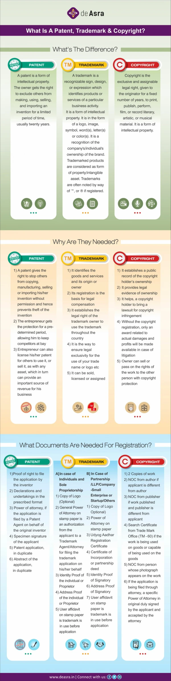
What is a Butterworth Filter? A Butterworth filter is a type of signal processing filter designed to have a frequency response as flat as possible in the passband. Hence the Butterworth filter is also known as “maximally flat magnitude filter”. It was invented in 1930 by the British engineer and physicist Stephen Butterworth in his paper titled “On the Theory of Filter Amplifiers”. The frequency response of the Butterworth filter is flat in the passband (i.e. a bandpass filter) and roll-offs towards zero in the stopband. The rate of roll-off response depends on the order of the filter. The numb The inductor and capacitor are reactive elements used in filters. But in the case of Butterworth filter only capacitors are used. So, the number of capacitors will decide the order of the filter. The inductor and capacitor are reactive elements used in filters. But in the case of Butterworth filter only capacitors are used. So, the number of capacitors will decide the order of the filter. Here, we will discuss the Butterworth filter with a low pass filter. Similarly, the high pass filter can be designed by just changing the position of resistance and capacitance.
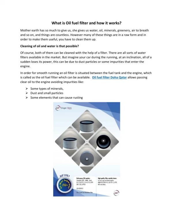
Butterworth Low Pass Filter Design While designing the filter, the designer tries to achieve a response near to the ideal filter. It is very difficult to match results with the exact ideal characteristic. We need to use complex higher-order filters to achieve the characteristic near to the ideal characteristic. If you increase the order of the filter, the number of cascade stages with the filter is also increased. But in practice, we cannot achieve Butterworth’s ideal frequency response. Because it produces excessive ripple in the passband. In Butterworth filter, mathematically it is possible to get flat frequency response from 0 Hz to the cut-off frequency at -3dB with no ripple. If the frequency is more than the cut-off frequency, it will roll-off towards zero with the rate of -20 dB/decade for the first-order filter. If you increase the order of the filter, the rate of a roll-off period is also increased. And for second-order, it is -40 dB/decade. The quality factor for the Butterworth filter is 0.707. The below figure shows the frequency response of the Butterworth filter for various orders of the filter. Frequency Response of Butterworth Filter. The generalized form of frequency response for nth-order Butterworth low-pass filter is;
Where, n=order ω=operating ωC= ε = maximum passband gain = Amax of the filter, ofcircuit frequency (passband frequency) Cut-offfrequency The below equation is used to find the value of ε. Where, H1 = minimum passband gain H0 = maximum passband gain 1.First-order Lowpass Butterworth Filter The lowpass filter is a filter that allows the signal with the frequency is lower than the cutoff frequency and attenuates the signals with the frequency is more than cutoff frequency. In the first-order filter, the number of reactive components is only one. The below figure shows the circuit diagram of the first-order lowpass Butterworth filter.
First-order Low Pass Butterworth Filter The low pass Butterworth filter is an active Low pass filter as it consists of the op- amp. This op-amp operates on non-inverting mode. Hence, the gain of the filter will decide by the resistor R1 and RF. And the cutoff frequency decides by R and C. Now, if you apply the voltage divider rule at point Va and find the voltage across a capacitor. It is given as; Because of the non-inverting configuration of an op-amp,
Where, fc = Cutoff Frequency f = Operating Frequency At very low frequency, f<<fc At cutoff frequency, f= fc At high frequency, f> fc The below figure shows the frequency response of first-order lowpass Butterworth filter.
Frequency Response of First-order Low Pass Butterworth Filter. 2.Second-order Butterworth Filter The second-order Butterworth filter consists of two reactive components. The circuit diagram of a second-order low pass Butterworth filter is as shown in the below figure. Second-order Low Pass Butterworth Filter
In this type of filter, resistor R and RF are the negative feedback of op-amp. And the cutoff frequency of the filter decides by R2, R3, C2, and C3. The second-order lowpass Butterworth filter consists of two back-to-back connected RC networks. And RL is the load resistance. First-order and second-order Butterworth filters are very important. Because we can get higher-order Butterworth filter by just cascading of the first-order and second- order Butterworth filters. Let’s analyse the circuit of second-order Butterworth filter, Apply Kirchhoff’s Current Law at point V1. Using potential divider rule at point Va Put the value of V1 in equation-(1)
Because of the non-inverting configuration of an op-amp, Where, Rearrange this equation,
Compare this equation with the standard form transfer function for second-order Butterworth filter. And that is, By comparing above equations, we can find the equation of cutoff frequency and overall gain for the second-order lowpass Butterworth filter. The gain of filter is, And the Cutoff frequency of filter is , Now, if we consider the value of R2 is same as R3 and the value of C2 is same as C3. Now if we put above values in transfer function,
From above equation, the quality factor Q is equal to, We can say that, the quality factor is only depends on the gain of filter. And the value of gain should not more than 3. If the value of gain is more than 3, the system will be unstable. The value of quality factor is 0.707 for the Butterworth filter. And if we put this value in equation of quality factor, we can find the value of gain. While designing the second-order Butterworth filter above relation must be satisfy. The frequency response of this filter is as shown in below figure.
Frequency Response of Second-order Low Pass Butterworth Filter. 3.Butterworth Filter Applications The applications of a Butterworth filter are listed below: Because of the maximal flat frequency response in the passband, it is used as an anti- aliasing filter in data converter applications. The Butterworth filter is used in the audio processing application. An efficient audio noise reduction tool can be developed using a Butterworth filter. It is also used in various communication and control systems. It is used in radar to design the display of radar target tracking. It is used for motion analysis. 4.Ideal Frequency Response for a Butterworth Filter
Note that the higher the Butterworth filter order, the higher the number of cascaded stages there are within the filter design, and the closer the filter becomes to the ideal “brick wall” response. In practice however, Butterworth’s ideal frequency response is unattainable as it produces excessive passband ripple. Where the generalised equation representing a “nth” Order Butterworth filter, the frequency response is given as: Where: n represents the filter order, Omega ω is equal to 2πƒ and Epsilon ε is the maximum pass band gain, (Amax). If Amax is defined at a frequency equal to the cut-off -3dB corner point (ƒc), ε will then be equal to one and therefore ε2 will also be one. However, if you now wish to define Amax at a different voltage gain value, for example 1dB, or 1.1220 (1dB = 20*logAmax) then the new value of epsilon, ε is found by:
Where: n represents the filter order, Omega ω is equal to 2πƒ and Epsilon ε is the maximum pass band gain, (Amax). If Amax is defined at a frequency equal to the cut-off -3dB corner point (ƒc), ε will then be equal to one and therefore ε2 will also be one. However, if you now wish to define Amax at a different voltage gain value, for example 1dB, or 1.1220 (1dB = 20*logAmax) then the new value of epsilon, ε is found by: Where: H0 = the Maximum Pass band Gain, Amax. H1 = the Minimum Pass band Gain. Transpose the equation to give: The Frequency Response of a filter can be defined mathematically by its Transfer Function with the standard Voltage Transfer Function H(jω) written as: Where: Vout = the output signal voltage. Vin = the input signal voltage. j = to the square root of -1 (√-1) ω = the radian frequency (2πƒ) Note: ( jω ) can also be written as ( s ) to denote the S-domain. and the resultant transfer function for a second-order low pass filter is given as:
Normalised Low Pass Butterworth Filter Polynomials To help in the design of his low pass filters, Butterworth produced standard tables of normalised second-order low pass polynomials given the values of coefficient that correspond to a cut-off corner frequency of 1 radian/sec.