Download
1 / 14
240 likes | 985 Views
Lecture 23. Filters I. What is a filter Passive filters Some common filters. What are filters?. Filters are electronic circuits which perform signal processing functions, specifically intended to remove unwanted signal components and/or enhance wanted ones. Common types of filters:

E N D
Lecture 23. Filters I • What is a filter • Passive filters • Some common filters
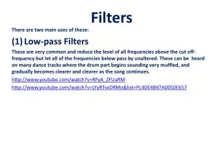
What are filters? • Filters are electronic circuits which perform signal processing functions, specifically intended to remove unwanted signal components and/or enhance wanted ones. • Common types of filters: • Low-pass: deliver low frequencies and eliminate high frequencies • High-pass: send on high frequencies and reject low frequencies • Band-pass: pass some particular range of frequencies, discard other frequencies outside that band • Band-rejection: stop a range of frequencies and pass all other frequencies (e.g., a special case is a notch filter)
Bode Plots of Common Filters Low Pass High Pass Gain Gain Frequency Frequency Band Pass Band Reject Gain Gain Frequency Frequency
Passive vs. Active filters • Passive filters: RLC components only, but gain < 1 • Active filters: op-amps with RC elements, and gain > 1
Passive Filters • Passive filters use R, L, C elements to achieve the desired filter Some Technical Terms: • The half-power frequency is the same as the break frequency (or corner frequency) and is located at the frequency where the magnitude is 1/2 of its maximum value • The resonance frequency, 0, is also referred to as the center frequency
First-Order Filter Circuits High Pass Low Pass R R VS + – Low Pass VS + – High Pass L C GR = R / (R + 1/sC) GC = (1/sC) / (R + 1/sC) HR = R / (R + sL) HL = sL / (R + sL)
Second-Order Filter Circuits Band Pass Z = R + 1/sC + sL HBP = R / Z HLP = (1/sC) / Z HHP = sL / Z HBR = HLP + HHP R Low Pass C VS + – Band Reject High Pass L
Higher Order Filters • We can use our knowledge of circuits, transfer functions and Bode plots to determine how to create higher order filters • For example, let’s outline the design of a third-order low-pass filter
Frequency & Time Domain Connections • First order circuit break frequency: break = 1/ • Second order circuit characteristic equation s2 + 20 s + 02 [ = 1/(2Q) ] (j)2 + 2(j) + 1 [ = 1/0 ] s2 + BW s + 02 s2 + R/L s + 1/(LC) [series RLC] Q value also determines damping and pole types Q < ½ ( > 1) overdamped, real & unequal roots Q = ½ ( = 1) critically damped, real & equal roots Q > ½ ( < 1) underdamped, complex conjugate pair
Time Domain Filter Response • It is straightforward to note the frequency domain behavior of the filter networks, but what is the response of these circuits in the time domain? • For example, how does a second-order band-pass filter respond to a step input?
Other types of filters • Butterworth – flat response in the passband and acceptable roll-off • Chebyshev – steeper roll-off but exhibits passband ripple (making it unsuitable for audio systems) • Bessel – yields a constant propagation delay • Elliptical – much more complicated
Butterworth filters • Butterworth – The Butterworth filter is designed to have a frequency response which is as flat as mathematically possible in the passband. Another name for them is 'maximally flat magnitude' filters. Example: A 3rd order Butterworth low pass filter. C2 = 4/3 farad, R4 = 1ohm, L1 = 3/2 and L3=1/2 H.
Butterworth filters nth order Butterworth filter. where n = order of filter ωc = cutoff frequency (approximately the -3dB frequency) G0 is the DC gain (gain at zero frequency The poles of this expression occur on a circle of radius ωc at equally spaced points As n approaches infinity, it becomes a rectangle function
Class Examples • Example 10-1 and 10-2 • Drill Problem 10-1