Download

1 / 37
420 likes | 1.19k Views
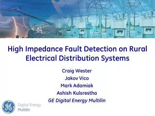
High Impedance Fault Detection on Rural Electrical Distribution Systems Craig Wester Jakov Vico Mark Adamiak Ashish Kulsrestha GE Digital Energy Multilin Overview Definitions & causes of Hi-Z faults Importance of Hi-Z detection Misconception about Hi-Z faults

E N D
High Impedance Fault Detection on Rural Electrical Distribution Systems Craig WesterJakov VicoMark AdamiakAshish KulsresthaGE Digital Energy Multilin
Overview • Definitions & causes of Hi-Z faults • Importance of Hi-Z detection • Misconception about Hi-Z faults • Characteristics of High Impedance (Hi-Z) Faults • Fault currents on various surfaces • Research and development at Texas A&M University • Hi-Z & Arc detection using Microprocessor-Based Technology • Implementation & response strategies • Field experiences • Summary
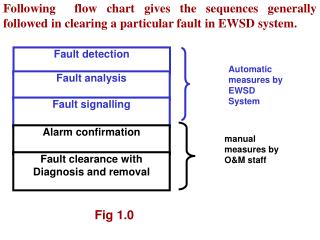
Definition of Hi-Z faults • An energized primary conductor in contact with a quasi-insulating object, such as a tree, structure or earth…..thus a high impedance (or Hi-Z) fault • Not detected by conventional phase or ground overcurrent protection (fuses or overcurrent relays) • Little threat of damage to power system equipment, but potential safety and fire hazard • Hi-Z faults produce primary current levels of 0 to 100 Amps • Seldom documented on trouble reports
Causes of Hi-Z faults • Broken line on ground (Downed Conductor) • Broken pole allowing line to contact a ground or conducting surface • Broken pole or tree limb allowing primary to sag • Contact with tree limb or other objects (Intermittent Arcing) • Contaminated or failing equipment (insulators, transformers, conductors, etc.)
Importance of Hi-Z detection Seasonal conditions impacts people & assets
Importance of Hi-Z detection Extreme weather conditions impacts people & assets
Importance of Hi-Z detection • If not detected and isolated, live Downed Conductors can be fatal to public and line crewmen • Hi-Z faults often arc and can be a significant fire hazard • Detect failing insulation before complete device failure which can lead to power outages and loss of production • Inability to detect Hi-Z faults can cost utilities liabilitiesand customer service issues • Performance has been verified under normal conditions (noisy feeders, arc furnaces, arc welders, capacitor switching, line switching and load tap changing) Hi-Z detection is about protecting people and assets
Misconceptions about Hi-Z faults Misconception: Properly set, overcurrent protection will trip and clear all faults on distribution feeder Reality:Hi-Z faults often draw less current (10 – 100 amps) than loads, making overcurrent protection unable to operate Misconception: Sensitive ground protection typically used to detect low ground current, will clear Hi-Z faults Reality:Unbalanced loads limit sensitivity of ground protection. Moreover, a down conductor can result in more balanced loads and reduced neutral current. This can easily mislead the low impedance protection element and no operation .
Misconceptions about Hi-Z faults . . . Misconception: Over time, fault current will increase and operate protection Reality:In most cases, fault current decreases as conductor burns, moisture evaporates, sand fuses, etc. overcurrent protection seldom operates after first minute Misconception: Faults always clear on my system Reality:Engineering staffs believe Hi-Z fault rate is low, but line crews report many downed conductors are still hot when they arrive on scene
10,000 1,000 AMPS 100 10 1 HiZ Fault Load Bolted Fault Introduction to Hi-Z Definition:A high-impedance (Hi-Z) fault is one that draws too little current to operate conventional overcurrent protection (fuses, relays, etc.). Hi-Z Fault Current Levels Conventional overcurrent protection is not able to detect Hi-Z
Introduction to Hi-Z • Hi-Z arcing fault current is rich in harmonics and non-harmonics. • Hi-Z fault current is erratic but tends to decrease over time, often stopping completely after minutes. • Hi-Z faults persist seconds to minutes….. to days
Fault currents on various surfaces Surface Fault current (A)Dry Asphalt 0Dry Sand 0Wet Asphalt 1Wet Sand 5Dry Sod 10Concrete (non-reinforced) 10Wet Sod 50Concrete (reinforced) 70 80-85% of all down conductors can be detected
Basics of Hi-Z Faults • Down Conductor occurs when live conductor breaks and falls on the ground • A break in the conductor usually leads to: • Drop in the load or • Momentary overcurrent due to falling conductor contacting a grounded object. • A Hi-Z fault often is accompanied by arcing at the point of the fault • Hi-Z fault without a broken conductor is termed as Intact Hi-Z condition and is caused by: • Failure of the conductor mounting system • Insulation failure • Inadvertent contact with external element (tree limb)
Characteristics of arcing faults • Little effect on voltage • Small fault current (10 – 100 Amps) • Current values will continue to fluctuate • Significant harmonic and non-harmonic current • No single parameter uniformly changing Normal System Behavior Hi-Z Fault Behavior
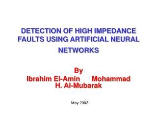
Research and development lead by Texas A&M University (TAMU) • Hundreds of staged fault tests since early 1990’s • At dedicated local facility • At multiple utilities across US • Important note: fault current was not artificially limited • Characterization of Hi-Z behavior • Multiple generations of prototypes • Staged faults assessed sensitivity to faults • Long-term installations assessed immunity to false trips • Long-term prototype installations established criteria for success and formed high-level system concepts
Communications • SOE • Oscillography • SCADA Trip Close Alarm Hi-Z & Arc detection • Apply on distribution breaker or recloser to detect Hi-Z faults • 4.16 to 34.5kV applications • Hi-Z detection will work on current alone - use relaying CTs • Voltage provides supplemental phase identification • Algorithm in service since 1992 on various hardware platforms
The following nine sophisticated algorithms are used: • Energy • Randomness • Expert Arc Detector • Load Event Detector • Load Analysis • Load Extraction • Arc Burst Pattern Analysis • Spectral Analysis • Arcing Suspected Identifier Over 20 year matured algorithms Hi-Z & Arc detection • Uses signature based expert pattern recognition system developed at Texas A&M University • Harmonic energy levels of currents in the arc is used for Hi-Z fault detection • The expert system techniques are designed to assure security and dependability
Hi-Z & Arc detection Detection Parameters • Odd harmonics (3rd, 5th, …) • Largest increase • Smallest relative increase • Even harmonics (2nd, 4th, …) • Small ambient level • Affected by inrush • Non harmonics (1/2, 1-1/2, 2-1/2, …) • Small ambient level • Voltage • Enhance security • Phase Identification • Learns ambient harmonic level and adjusts frequently
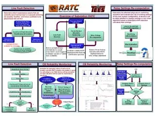
Hi-Z & Arc detection High Impedance Fault Detection Block Diagram
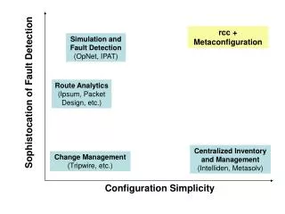
Implementation Strategy Contrast in Detection Goals - Overcurrent vs. High Impedance • Sufficient current vs. low current • Equipment damage vs. safety/fire prevention Electrical or Mechanical Detection Options • Electrical options applied one per feeder or recloser • Mechanical options applied in certain areas (schools and churches) • Mechanical options can detect sagging conductors
Implementation Strategy Customer Service • A priority due to increasing competition • Hi-Z faults can cause service interruptions and deliver substandard power to users • Applying electrical Hi-Z detection, allows utilities to respond quicker to Hi-Z occurrences • Accurate, dependable and secure operation is very important • Inform customers of potential problems • Response procedures can be created • 95-98% complete fault detection possible(low impedance + high impedance)
Implementation Strategy Feeder Selection • Unreasonable to apply Hi-Z detection on every feeder at once due to expense Circuits with: • Past Hi-Z events • Population dense circuits • Fire prone areas • Older circuits with undersized conductors • 4 - 35kV circuits • Overhead construction
Arcing fault response strategy Condition Primary Response Secondary Response Arcing Suspected Alarm -- Arcing Detected Alarm Trip Downed Conductor Trip Alarm • No device can protect from initial contact • Disable reclosing after detection of Hi-Z
Hi-Z Based Feeder Sectionalizing • Coordination via settings & communication B R R R
PEPCO • Serves Washington DC and parts of Maryland • Covers an area of 640 sq. mi. • Provides power to over 2,000,000 customers • Distribution system of 620 13kV overhead feeders • Study based on 280 installed Hi-Z relays over a 2 year period • Hi-Z relays were set biased toward security
Study Methodology • Candidate Faults for Study • Operator logs • Line Broken • Still Energized -- OR -- • Relay Hi-Z target - Checked Weekly Relays were set biased towards security
Study Results • Study based on 560 relay-years of operation • Several hundred broken wires recorded during study • 48 “Downed/Energized” faults recorded • From the remaining 48 “Downed/Energized” faults • 46 of the 48 relays indicated “Arcing” – 96% • 28 of the 48 relays reported “Downed Conductors” – 58% • 80% of the 28 “Downed Conductors” were tripped by Low Set Instantaneous & successfully reclosed Only 2 false operations in 560 Relay-Years of Operation!
Other Installations Experience to date of Hi-Z Algorithms • The ratio of “detected” downed conductors to the total population of downed conductors is 80-85%. • Investigation based on a periodic “arc detection” alarm lead to detect a motor failure at a customer site • Arcing due to loose transformer bushing was detected by Hi-Z algorithms • A house fire was successfully detected and feeder tripped and locked out • A downed conductor on an asphalt surface found paths through cracks in the asphalt, which lead to “down conductor” detection. • Intermittent arcing faults due to contact with tree limbs Secure determination of Down Conductor & Arcing Conditions
Summary • HiZ faults happen . . . and result in: • Personnel hazard • Property damage • Poor customer service • Effective technology has been demonstrated to: • Reliably detect HiZ faults • Detect arcing conditions on system • Securely report Downed Conductors • Safely trip feeders with Downed Conductors