Download
1 / 21
240 likes | 497 Views
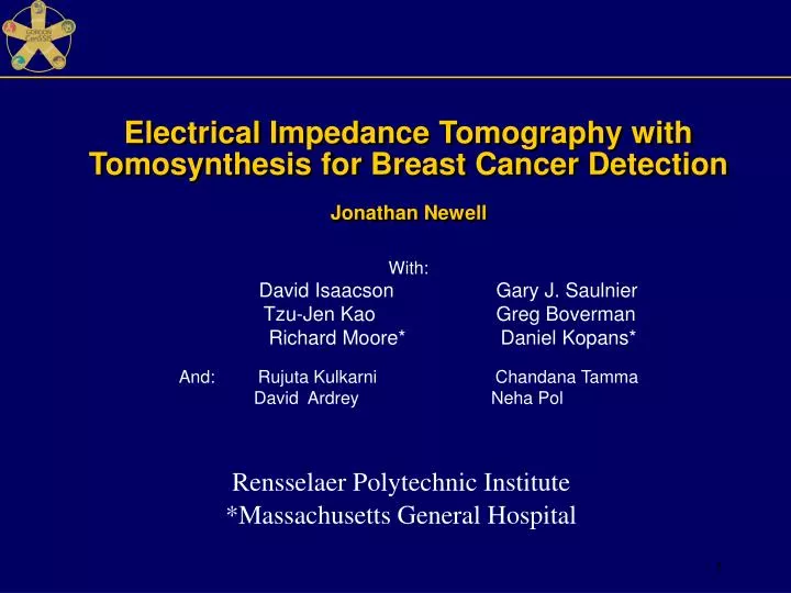
Electrical Impedance Tomography with Tomosynthesis for Breast Cancer Detection Jonathan Newell. With: David Isaacson Gary J. Saulnier Tzu-Jen Kao Greg Boverman Richard Moore* Daniel Kopans*

E N D
Electrical Impedance Tomography with Tomosynthesis for Breast Cancer DetectionJonathan Newell With: David Isaacson Gary J. Saulnier Tzu-Jen Kao Greg Boverman Richard Moore* Daniel Kopans* And: Rujuta Kulkarni Chandana Tamma David Ardrey Neha Pol RensselaerPolytechnicInstitute *Massachusetts General Hospital
EIT electrodes added to mammography machine. • 1 : 2 : 4 : 2 : 1 is the ratio of the mesh thicknesses. • Only the center layer, III, is displayed in the results.
EIT Instrumentation ACT 4 with Tomosynthesis unit Radiolucent electrode array
Co-registration of EIT and Tomo Images To find the electrode position, display the slice containing the electrodes. Superimpose the mesh grid with correct scale. Slice 15 of 91 HS_14R Normal Then select the desired tomosynthesis layer. Slice 50 of 91
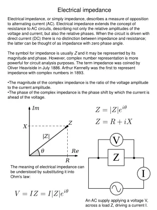
Admittance Loci: format for summaries of EIS data Results of in-vitro studies of excised breast tissue.Jossinet & Schmitt 1999
HS25_L: Invasive Ductal Carcinoma ROI 1 ROI 2
LCM Image 700 Y Ym 0 compute for each voxel Linear Correlation Measure –LCM
700 0 LCM Image of invasive ductal CA (HS25_L) Gray scale image of LCM
HS21_R: Fibroadenoma in the upper box ROI 1 ROI 2
LCM Image of fibroadenoma (HS21_R) 350 0 Gray scale image of LCM
HS10_L: Invasive Ductal CA“Proliferation is worrisome” ROI 1 ROI 2
LCM Image of invasive ductal CA (HS10_L) 1300 0 Gray scale image of LCM
LCM for 11 normal breasts 300 0 There are 120 EIS plots for layer 3 in each patient. The distribution of the LCM parameter in these plots is shown.
LCM for the regions of interest in 4 patients Hyalinized Fibroadenoma Invasive ductal carcinoma Normal Normal The distributions of the LCM for the regions of interest identified. Note the LCM values are much larger for voxels associated with the malignant lesions.
LCM on the same scale for a normal subject, a fibroadenoma and two carcinomas Normal Breast Fibroadenoma Invasive Ductal Carcinoma Invasive Ductal Carcinoma
Conclusions • We have discovered a quantitative parameter derived from the admittance spectra that is markedly different in malignancy from normal breast tissues. • This parameter is location-specific to the tumor. • We need to study more patients with more benign lesions and tumors in order to evaluate the clinical potential of this parameter to improve the sensitivity and specificity of breast cancer screening. • We will present additional details about our system and its results in four posters at this meeting. See Kao, Boverman, Kulkarni and Tamma.
Summary of first 38 patients accrued • Total patient studied: 37-7 = 30 • First 7 patients were needed to develop correct operational procedures. • 19 breasts are underwent biopsy • 7 of these were reported as CA • 4 breasts of these were located outside of the electrode region. • 3 CA breasts are OK for analysis
Threshold for Parameter, Straightness image • After preliminary study, we can set a threshold for normal or abnormal EIS plot. • 400 will be the first guess with these patient data. • The previous image will be show again with full scale set to 700.