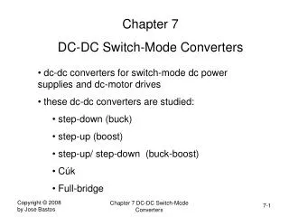
Chapter 4 DC Ammeter
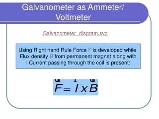
Chapter 4 DC Ammeter. Galvanometer is a PMMC instrument designed to be sensitive to extremely low current levels. The simplest galvanometer is a very sensitive instrument with the type of center-zero scale. The torque equation for a galvanometer is exactly as discussed in the previous section.

Chapter 4 DC Ammeter
E N D
Presentation Transcript
Chapter 4 DC Ammeter • Galvanometer • is a PMMC instrument designed to be sensitive to extremely low current levels. • The simplest galvanometer is a very sensitive instrument with the type of center-zero scale. • The torque equation for a galvanometer is exactly as discussed in the previous section. • The most sensitive moving-coil galvanometer use taut-band suspension, and the controlling torque is generated by the twist in the suspension ribbon.
With the moving-coil weight reduced to the lowest possible minimum for greatest sensitivity, the weight of t he pointer can create a problem. The solution is by mounting a small mirror on the moving coil instead of a pointer.
The mirror reflects a beam of light on to a scale. This makes light-beam galvanometers sensitive to much lower current levels than pointer instruments • Current sensitivity galvanometer • Voltage sensitivity galvanometer • Galvanometers are often employed to detect zero current or voltage in a circuit rather than to measure the actual level of current or voltage.
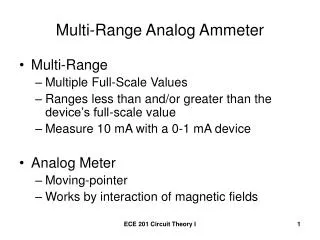
DC Ammeter • is always connected in series • low internal resistance • maximum pointer deflection is produced by a very small current • For a large currents, the instrument must be modified by connecting a very low shunt resister • Extension of Ranges of Ammeter • Single Shunt Type of Ammeter
Example 4.1: An ammeter as shown in Figure 3-9 has a PMMC instrument with a coil resistance of Rm = 99 and FSD current of 0.1 mA. Shunt resistance Rs = 1. Determine the total current passing through the ammeter at (a) FSD, (b) 0.5 FSD, and 0.25 FSD
Solution (a) At FSD (b) At 0.5 FSD (b) At 0.25 FSD
Example 4.2: A PMMC instrument has FSD of 100 A and a coil resistance of 1 k. Calculate the required shunt resistance value to convert the instrument into an ammeter with (a) FSD = 100 mA and (b) FSD = 1 A. Solution (a) FSD = 100 mA (b) FSD = 1 A
Swamping Resistance • The moving coil in a PMMC instrument is wound with thin copper wire, and its resistance can change significantly when its temperature changes. • The heating effect of the coil current may be enough to produce a resistance change, which will introduce an error. • To minimize the error, a swamping resistance made of manganin or constantan is connected in series with the coil (manganin and constantan have resistance temperature coefficients very close to zero.
The ammeter shunt must also be made of manganin or constantan to avoid shunt resistance variations with temperature. • Multirange Ammeters • Make-before-break switch • The instrument is not left without a shunt in parallel with it. • During switching there are actually two shunts in parallel with the instrument.
Ayrton Shunt • At B • Total resistance R1+R2+R3 • Meter resistance Rm • At C • Total resistance R1+R2 • Meter resistance Rm+R3 • At D?
Example 4.3: A PMMC instrument has a three-resistor Ayrton shunt connected across it to make an ammeter as shown in Figure 3-13. The resistance values are R1 = 0.05, R2 = 0.45 and R3 = 4.5. The meter has Rm = 1k and FSD = 50A. Calculate the three ranges of the ammeter. Solution Switch at contact B: Switch at contact C:
Switch at contact C: • Internal Ammeter Resistance: Rin • Ammeter Loading Effects • Internal resistance of ideal ammeter is zero Ohm, but in practice, the internal resistance has some values which affect the measurement results. • This error can be reduced by using higher range of measurement.
To calculate the relationship between the trued value and the measured value
Example 4.4 For a DC Circuit as shown in Figure below, given R1=2k, R2=1k with voltage of 2V. By measuring the current flow through R3 with a dc ammeter with internal resistance of Rin = 100Ω, calculate percentage of accuracy and percentage of error. Solution