Download
1 / 29
600 likes | 2.13k Views
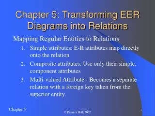
Chapter 5: Transforming EER Diagrams into Relations. Mapping Regular Entities to Relations Simple attributes: E-R attributes map directly onto the relation Composite attributes: Use only their simple, component attributes

E N D
Chapter 5: Transforming EER Diagrams into Relations Mapping Regular Entities to Relations • Simple attributes: E-R attributes map directly onto the relation • Composite attributes: Use only their simple, component attributes • Multi-valued Attribute - Becomes a separate relation with a foreign key taken from the superior entity © Prentice Hall, 2002
Figure 5-8: Mapping a regular entity (a) CUSTOMER entity type with simple attributes (b) CUSTOMER relation © Prentice Hall, 2002
Figure 5-9: Mapping a composite attribute (a) CUSTOMER entity type with composite attribute (b) CUSTOMER relation with address detail © Prentice Hall, 2002
Multivalued attribute becomes a separate relation with foreign key (b) Figure 5-10: Mapping a multivalued attribute (a) 1 – to – many relationship between original entity and new relation © Prentice Hall, 2002
Transforming EER Diagrams into Relations Mapping Weak Entities • Becomes a separate relation with a foreign key taken from the superior entity • Primary key composed of: • Partial identifier of weak entity • Primary key of identifying relation (strong entity) © Prentice Hall, 2002
Figure 5-11: Example of mapping a weak entity (a) Weak entity DEPENDENT © Prentice Hall, 2002
Composite primary key Figure 5-11(b) Relations resulting from weak entity NOTE: the domain constraint for the foreign key should NOT allow null value if DEPENDENT is a weak entity Foreign key © Prentice Hall, 2002
Transforming EER Diagrams into Relations Mapping Binary Relationships • One-to-Many - Primary key on the one side becomes a foreign key on the many side • One-to-One - Primary key on the mandatory side becomes a foreign key on the optional side • Many-to-Many - Create a new relation with the primary keys of the two entities as its primary key © Prentice Hall, 2002
NULL Values in Foreign Keys • Whether or not a Foreign Key can have NULL values depends on the minimum cardinality of the concerned relationship • Minimum cardinality of 0 represented as NULL allowed for foreign key columns • Minimum cardinality of 1 represented as NULL disallowed for foreign key columns © Prentice Hall, 2002
Figure 5-12: Example of mapping a 1:M relationship (a) Relationship between customers and orders Note the mandatory one © Prentice Hall, 2002
Figure 5-12(b) Mapping the relationship Again, no null value in the foreign key…this is because of the mandatory minimum cardinality Foreign key © Prentice Hall, 2002
Figure 5-14: Mapping a binary 1:1 relationship (a) Binary 1:1 relationship © Prentice Hall, 2002
Figure 5-14(b) Resulting relations © Prentice Hall, 2002
The Supplies relationship will need to become a separate relation Figure 5-13: Example of mapping an M:N relationship (a) ER diagram (M:N) © Prentice Hall, 2002
Composite primary key Foreign key Foreign key Figure 5-13(b) Three resulting relations New intersection relation © Prentice Hall, 2002
Transforming EER Diagrams into Relations Mapping Associative Entities • Identifier Not Assigned • Default primary key for the association relation is composed of the primary keys of the two entities (as in M:N relationship) • Identifier Assigned • It is natural and familiar to end-users • Default identifier may not be unique © Prentice Hall, 2002
Figure 5-15: Mapping an associative entity (a) Associative entity © Prentice Hall, 2002
Figure 5-15(b) Three resulting relations © Prentice Hall, 2002
Transforming EER Diagrams into Relations Mapping Unary Relationships • One-to-Many - Recursive foreign key in the same relation • Many-to-Many - Two relations: • One for the entity type • One for an associative relation in which the primary key has two attributes, both taken from the primary key of the entity © Prentice Hall, 2002
Figure 5-17: Mapping a unary 1:N relationship (a) EMPLOYEE entity with Manages relationship (b) EMPLOYEE relation with recursive foreign key © Prentice Hall, 2002
Figure 5-18: Mapping a unary M:N relationship (a) Bill-of-materials relationships (M:N) (b) ITEM and COMPONENT relations © Prentice Hall, 2002
Transforming EER Diagrams into Relations Mapping Ternary (and n-ary) Relationships • One relation for each entity and one for the associative entity • Associative entity has foreign keys to each entity in the relationship © Prentice Hall, 2002
Figure 5-19: Mapping a ternary relationship (a) Ternary relationship with associative entity © Prentice Hall, 2002
Figure 5-19(b) Mapping the ternary relationship Remember that the primary key MUST be unique © Prentice Hall, 2002
Transforming EER Diagrams into Relations Mapping Supertype/Subtype Relationships • One relation for supertype and for each subtype • Supertype attributes (including identifier and subtype discriminator) go into supertype relation • Subtype attributes go into each subtype; primary key of supertype relation also becomes primary key of subtype relation • 1:1 relationship established between supertype and each subtype, with supertype as primary table © Prentice Hall, 2002
Figure 5-20: Supertype/subtype relationships © Prentice Hall, 2002
Figure 5-21: Mapping Supertype/subtype relationships to relations © Prentice Hall, 2002
In-Class Exercise: Transform the following ERD to a relational structure FNAME LNAME SALARY SSN JOBCODE EMP# EMPLOYEE MARRIED-TO DIRECT WORK-IN DIVISION MANAGE BELONG-TO DEPARTMENT DIVNAME BLDG DIVNAME DEPTNAME DEPT# © Prentice Hall, 2002
Example Tables © Prentice Hall, 2002