Download

1 / 55
690 likes | 2.47k Views
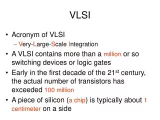
VLSI stands for Very Large Scale integration is the art of integrating millions of transistors on a Silicon Chip. Researchers are working to incorporate large scale integration of electronic devices on a single silica chip “Integrated Circuit or IC” to fulfill the market demand. Here, in this presentation we will learn introduction and history of VLSI, VLSI Design Style and Flow, VLSI Design Approaches, CPLD, FPGA, Programmable Logic Arrays, Xilinx vs. Altera Design tools, flow and files.

E N D
V L S I WELCOME LaveshKumath Head, R & D (VLSI Division ) Scientech Technologies Pvt. Ltd., Indore lkumath@scientech.bz
Basics of VLSI THE ART OF VLSI
Power Density Area Speed Features Functionality Semi conductor Diodes DTL Transistors FET BJT – TTL,RTL, ECL MOSFET Gates JFET N MOS P MOS CMOS ICs N Chan P Chan Gates SSI MSI LSI ICs SSI MSI LSI VLSI endless Journey……
General Design Flow…. TTL Logic Design Specification Truth Table Boolean Expression Implementation Logic minimization and multilevel logic optimization Cost and performance requirement Available Inventory
Digital Design Process 1. Design Specifications 2. Truth Table A B C D Logic 2 or >2 I/P = 1 then O/P 1 O/P = X AB 00 01 11 10 /CD 00 01 11 10 3. Reduce Expression Boolean Eq. -> X = AB + CD + BD + BC + AD + AC OR X’ = A’B’C’ + A’B’D’ + A’C’D’ + B’C’D’
Digital Design Process • Design Specifications • Truth Table • Reduction using Boolean or K Map 4. Minimize of Device or No. of Level i.e. Cost Vs Performance (Min Prop. Delay) 5. Examine Available Inventory 6. Eqn Re-written in NAND-NAND implementation Few Device and Few logic i.e. Less Cost and Better Performance Boolean Eq. -> X = {(AB)’. (CD)’ . (BD)’ .(BC)’. (AD)’ .(AC)’ }’ -->2 - 7400, 1 - 7430, 2 level of logic 1 - 7474 for synchronization 1 2 Boolean Eq. -> X = AB + CD + BD + BC + AD + AC --> 2 - 7408, 3 - 7432, 3 level of logic 1 - 7474 for synchronization
Basics of VLSI ……….. • VLSI Introduction • History of VLSI. • Why VLSI …. ? • VLSI Design Styles • VLSI Design Flows • VLSI Design Approaches • Xilinx Vs Altera
VERY LARGE SCALE INTEGRATION “ Is the art of integrating millions of transistors on a Silicon Chip ”
History of IC Design The First Transistor “ A device called a transistor, which has several applications In radio where a vacuum tube ordinarily is employed, was demonstrated for the first time at Bell Telephone Laboratories, 463 West Street, where it was invented.” 23 December 1947 First point contact transistor (germanium), 1947 John Bardeen and Walter Brattain Bell Laboratories
- Evolution of ICs - Vacuum tubes Transistors Gates ICs High Performance High Reliability High complexity or small Area High applicability Low Power Dissipation Low power consumption Low Cost Fast Design time Simple Design Process ? Integrated Circuits IC is a collection of Electronic Circuits made by simultaneously forming individual Transistors, Diodes and Resistors on a small chip of Semiconductor material, typically silicon that are interconnected to one another with a metal, such as aluminum, deposited on the chip surface.
The Progressive Trend of IC Technology Integration Level Year Number of Transistors SSI - Individual Gates 1950s Less than 10^2 MSI - Counter, Shift Reg. 1960s 10^2 – 10^3 LSI - Small Logic Function 1970s 10^3 – 10^5 VLSI - Large Logic Function 1980s 10^5 – 10^7 1990s 10^7 – 10^9 2000s Over 10^9
Moore’s Law In 1965, Intel co-founder Gordon Moore saw the future. His prediction, now popularly known asMoore's Law, states that “The number of transistors on a chip doubles about every two years” Other Trends - Transistor Count – Number of Transistor doubles every 2-3 Yrs Clock Frequency – Clock Frequency doubles every 2.168 Yrs Features Size – Gate Length is divided by 2 every 5.43 Yrs http://www.intel.com/technology/silicon/mooreslaw/
Key feature: transistor length L VLSI Technology - CMOS Transistors 2002: L=130nm 2003: L=90nm 2006: L=65nm
IEEE Spectrum, July 1999 Special report: “The 100-million transistor IC” 2002 and beyond ? Semiconductor Industry Association (SIA) Road Map, 1998 Update 1999 20022014 Technology (nm) 180 130 35 Wafer diameter (mm) 300 300 450 Memory-samples (bits) 1G 4G 1T Transistors/cm2 (P) 6.2M 18M 390M Wiring levels (maximum) 6-7 7 10 Clock, local (MHz) 1250 2100 10000 Chip size: DRAM (mm2) 400 560 2240 Chip size: mP (mm2) 340 430 901 Power supply (V) 1.5-1.8 1.2-1.5 0.37-0.42 Maximum Power (W) 90 130 183 Number of pins (P) 700 957 3350 These scaling trends will allow the electronics market to growth at 15% / year
Power & Clock Frequencies • Power Consumption, Clock frequency, Supply Voltage are related as follows :- Capacitance Supply Voltage Clock Frequency
Why VLSI Design ? • Large Scale Integration - • Size ….. <<< • Speed …. >>> • Power …. <<< • Integration reduce manufacturing costs • (almost) no manual assembly • Money Vs Performance
VLSI Design Styles Integrated Circuits 4 1 2 3 User Programmable Semi-Custom ASICs Full-Custom ASICs System-On CHIP PLD FPGA PAL PLA SPLD CPLD Gates MUX LUT (Look-Up Table)
Programmable Logic (PLD, FPGA) Application-Specific Integrated Circuit (ASIC) Full Custom System-on-Chip VLSI Design Styles
VLSI Design Styles Integrated Circuits 3 2 1 4 Semi-Custom ASICs Full-Custom ASICs User Programmable System-On CHIP PLD FPGA PAL PLA SPLD CPLD Gates MUX LUT (Look-Up Table)
Pre-manufactured components with programmable interconnect CAD tools greatly reduce design effort Low Design Cost Low NRE Cost High Unit Cost Lower Performance as compared to ASIC better than General digital design 1. Programmable Logic (PLDs, FPGAs)
Logic Circuits …… FPLD
FPLD Representatives • PLA - Programmable Logic Arrays • PAL - Programmable Array Logic • CPLD - Complex Programmable Logic Devices • FPGA - Field Programmable Gate Arrays PLD
What is a CPLD ? • Complex Programmable Logic Devices (CPLD) are another way to extend the density of the simple PLD. • CPLD uses less board space, improve reliability, and reduce cost. • CPLD contains multiple logic block, which communicate with one another using Signals routed via a programmable interconnect. • Easily Routed. • CPLDs are great at handling wide and complex gating at blistering speeds e.g. 5ns which is equivalent to 200MHz.
CPLD Architecture Complex Programmable Logic Devices
Why use a CPLD ? • Ease of Design • Lower Development Costs • More Product Revenue • Reduced Board Area • Reconfigurable • Flexible
Evolution of PLD: FPGA contains a set of basic functions (gates, FFs, memory cells) • Difficult extending CPLDs architectures to higher densities - adifferent approach is needed • FPGAs comprise an array of uncommited circuit elements, called logic blocks, and interconnect resources • FPGA configuration is performed through programming by the end user. Xilinx FPGA Configuration
Field Programmable Gate Array General FPGA Architecture
Reasonably Cheap at low volume Good for low-volume parts, more expensive than IC for high-volume parts Can migrate from SRAM based to fuse based when volume ramps up Short Design Cycle (~1sec programming time) Reprogrammable Can download bug fix into units you’ve already shipped Large capacity (100 million gates or so .…. More flexible than PLDs -- can have internal state More compact than MSI/SSI FPGAs -- Pros
FPGA’s -- Cons • Lower capacity, speed and higher power consumption than building an ASIC • Sub-optimal mapping of logic into CLB’s – often 60% utilization • Much lower clock frequency • Less dense layout and placement and slower operation due to programmability • Overhead of configurable interconnect and logic blocks • PLDs may be faster than FPGA for designs they can handle • Need sophisticated tools to map design to FPGA
Key Factors For Comparing FPGAs • Logic density • Clock management • On-chip memory • DSP capabilities • I/O compatibility • Software support & other design services
Programmable Logic (PLDs, FPGAs) • Pre-manufactured components with programmable interconnect • CAD tools greatly reduce design effort • Low Design Cost / Low NRE Cost / High Unit Cost • Lower Performance Medium Type Design, Combinational CLB – LUT, MUX, FF, I/Os, PI, DLL, Sequential
Save Valuable Board Space Power Requirement is low Increases Performance Design Security Lower Standby and Switching Current Integration increases Design Reliability I/Os Delay Reduces Flexibility No NRC Cost Low Time to market Process Automation High Density ……… or Complex Design ADVANTAGES OF PROGRAMMABLE LOGICS
How to Cope with Complexity ? Electronic Design Automation (EDA) • Computer Aided Design (CAD) …. Front - end • Computer Aided Engineering (CAE) …. Back - end Simulation – H-Spice (Synopsis), Spector (Cadance), Spector RF, H-Sim (Synopsis for Digital), DA (Design Architect Mentor), Co-Sim (Synopsis for Mixed), FineSim SPICE, Fine Wave (Megma) Synthesis & Implementation - DC (Synopsis), ISE (Xilinx), Quartus (Altera), Blast – Integrated RTL-to-GDSII Flow (Megma) Timing Analysis & Verification – Prime Time, Formality – (Synopsis), DRC & LVS (Magma), Modelsim – Mentor, Physical Design – Astro, Layout – Vertuoso (Cadance), Magic, L-Edit
General Tool Flow for PLDs DesignEntry Configurable Logic VHDL or Verilog code Device independent LUT’s or Gates Flip-flop Synthesis Device type , Constraint Configurable Switch Matrix Transistor Switch Muxes Implementation Gate Level circuit Device Type, Constraints Floor Planning Configuration Memory BitStream Volatile Non-volatile User Constraint file Download cable PLD Chip Software
VLSI Design Styles Integrated Circuits 2 3 1 4 Semi-Custom ASICs Full-Custom ASICs User Programmable System-On CHIP FPGA PLD Gates MUX LUT (Look-Up Table) PAL PLA SPLD CPLD
Constrained design using pre-designed (and sometimes pre-manufactured) components Also called semi-custom design CAD tools greatly reduce design effort Low Design Cost / High NRE Cost / Med. Unit Cost Medium Performance 2. Application-Specific Integrated Circuit (ASIC)
Two competing implementation approaches ASIC Application Specific Integrated Circuit FPGA Field Programmable Gate Array • Designs must be sent • for expensive and time • consuming fabrication • in semiconductor foundry • Bought off the shelf • and reconfigured by • designers themselves • No physical layout design; • design ends with • a bitstream used • to configure a device • Designed all the way • from behavioral description • to physical layout
FPGAs ASICs Off-the-shelf High performance Low development cost Low power Short time to market Low cost in high volumes Re-configurability Balance ……….
Which way to Go FPGA=FieldProgrammableGateArray flexibility of software + speed of hardware design ASIC=ApplicationSpecificIntegratedCircuits tailor-made on demand for specific applications
Each circuit element carefully “handcrafted” NO use of any Library. Huge design effort. High Design & NRE Costs High Performance Typically used for high-volume applications Design Productivity is Very Low 3. Full Custom Design
4. System-on-a-chip (SOC) • Idea: combine several large blocks • Predesigned custom cores (e.g., microcontroller) - “intellectual property” (IP) • ASIC logic for special-purpose hardware • Programmable Logic (PLD, FPGA) • Analog • Open issues • Keeping design cost low • Verifying correctness of design
Front-end & Back-end Back-end Front-end • Floorplanning • Placement • Routing • GDSII (final Output, Foundary) • Logic design (RTL) • Simulation • Synthesis • Implementation Verification
Physical design vs. Building a City • A City • Buildings • City planner • Architect • Builder • Electrician • Microelectronic system • ASICs • System partitioning • ASIC floorplanning • Placement • Routing
Programmable Logic Vendors • Xilinx - Xilinx Foundation Series. • Altera - Max Plus – II • Lattice - ISP Expert Compiler • Actel - Actel’s Designer Series FPGA Development System • Lucent - ORCA Foundry Development System • Cypress - Warp2 • Atmel - FPGA Integrated Development System ( IDS ) • QuickLogic - QuickWorks • Gatefield - ASIC master
Key players: Xilinx, Altera, Lattice, Actel PLD market estimated at $57 billion and rapidly growing The goal is to expand the market: by lowering per-unit cost to attack the low-end market by increasing speed capabilities to attack the high-end market XILINX Vs ALTRA Design Flow, Tools and Files PLD market share
XILINX Vs ALETRA • Virtex and Stratix families are direct opponents, as are Spartan and Cyclone
Schematic editor • HDL (.v or .vhd) Text – (EDIF, XNF) XST + GUI = NGC FPGA Design Flow – Xilinx - ISE Design Entry Design Verification Functional Simulation Library Design Synthesis UCF Design Implementation Net list + Constraints = NGD *Translate *Mapping *P & R *Fitting *Bit stream Generation Static Timing Analysis NCD – Native Circuit Description VM6 -------- CPLD Timing Simulation .BIT or .JED In Circuit Verification Download to Device