Download
1 / 6
60 likes | 125 Views
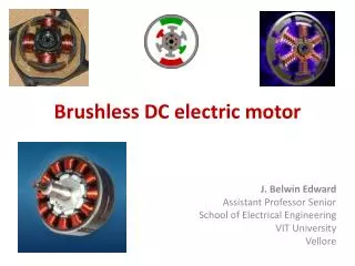
A brushless motor sensor is an electronic circuit that senses the position of a brushless motor. This circuit is used to control the speed of the motor.

E N D
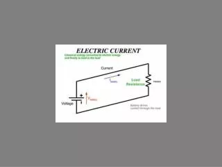
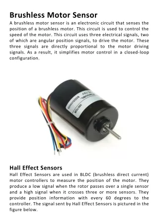
Brushless Motor Sensor A brushless motor sensor is an electronic circuit that senses the position of a brushless motor. This circuit is used to control the speed of the motor. This circuit uses three electrical signals, two of which are angular position signals, to drive the motor. These three signals are directly proportional to the motor driving signals. As a result, it simplifies motor control in a closed-loop configuration. Hall Effect Sensors Hall Effect Sensors are used in BLDC (brushless direct current) motor controllers to measure the position of the motor. They produce a low signal when the rotor passes over a single sensor and a high signal when it crosses three or more sensors. They provide position information with every 60 degrees to the controller. The signal sent by Hall Effect Sensors is pictured in the figure below.
Hall effect sensors work by measuring magnetic fields. The output signal is proportional to the strength and density of the magnetic field. When a magnetic field is passed over a Hall effect sensor, an output voltage is generated. Depending on the voltage drop, the signal is analogue or digital. Stator Resistance Adaptation In sensorless systems, a vital step in obtaining optimal performance is stator resistance adaptation. This technique allows for accurate estimation of stator resistance and flux even at low speed. This method is particularly important for systems that require a low-speed operation. It is also useful in low-speed systems because the voltage at the stator is small, and the voltage decreases in direct proportion to the resistive voltage drop and frequency of the motor.
Stator resistance adaptation can be achieved by several different approaches. One such method is the use of a model reference adaptive system (MRAS). This technique is highly efficient, fast, and easy to implement. AFFO Scheme for Brushless Motor Control The AFFO scheme for brushless motor control consists of three sensors with a 60-degree relative offset. The signals produced by the sensors are converted to three bits each and sent to a microprocessor for processing. This microprocessor performs commutation, phase-delay correction, and gate control. The resulting signals control the speed of the motor and are useful for closed-loop motor control.
The AFFO scheme is based on the Lyapunov stability criterion, and it estimates the rotor speed and stator resistance simultaneously. The scheme is not computationally intensive, but it can become unstable when the gain matrix is non-zero. A nonlinear magnetic model can be used to simulate steady-state conditions. Detection of Back-EMF The back-EMF produced by a Brushless Motor Sensor is a measurable electric field. Its magnitude is proportional to the motor speed and is zero at standstill. Due to the large signal-to- noise ratio of measured terminal voltages, the sensorless back- EMF detection method is not useful for motors with low speeds. As a result, it is recommended to use the improved back-EMF sensing scheme. This scheme can be used to run the motor over a wide speed range. Another advantage of this method is that it does not require a manufactured neutral voltage. This method also does not require a large amount of filtering, which reduces the system’s cost. The ST72141 from STMicroelectronics is a microcontroller-based back-EMF sensor that combines an analogue detection circuit with motor control peripherals. The sensor can extract the true
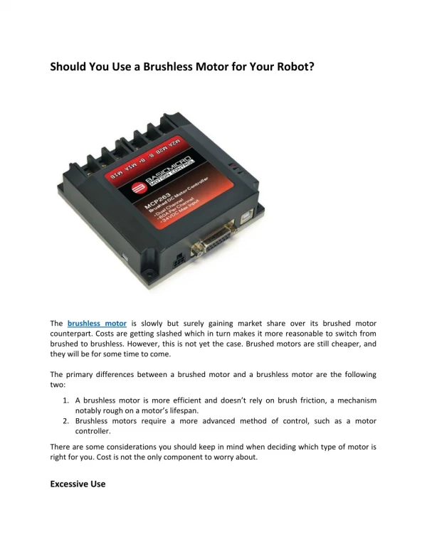
back-EMF zero-crossing point from the terminal voltage. The signal is then fed into the microcontroller through a current- limiting resistor. Unlike the previous methods, this method does not attenuate the feedback signal. Application of Brushless Motor Sensor Brushless motors are versatile tools that can be used for various applications. The use of a sensor helps in ensuring that the motors are operating in a safe manner and without causing any damage to them. There are several methods to realize this, including using the Maxon method, which sets new standards in reliability and precision.
It is a small and robust device that can be installed inside the motor casing. In addition, it can withstand high temperatures, pressures, and even chemical attacks. These sensors also help in preventing severe motor failures, which improves the reliability of control systems.