Download
1 / 27
300 likes | 867 Views
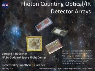
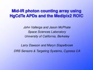
Mid-IR photon counting array using HgCdTe APDs and the Medipix2 ROIC. John Vallerga and Jason McPhate Space Sciences Laboratory University of California, Berkeley Larry Dawson and Maryn Stapelbroek DRS Sensors & Targeting Systems, Cypress CA. Q. V ± s v. Events. Count. ADC. (x,y,t).

E N D
Mid-IR photon counting array using HgCdTe APDs and the Medipix2 ROIC John Vallerga and Jason McPhate Space Sciences Laboratory University of California, Berkeley Larry Dawson and Maryn Stapelbroek DRS Sensors & Targeting Systems, Cypress CA
Q V ± sv Events Count ADC (x,y,t) Threshold Events ± sEvents Photon counting Charge integrating
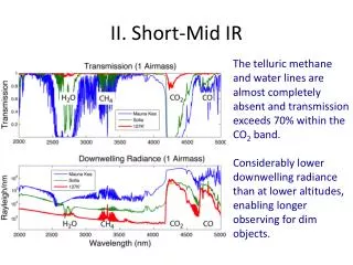
Motivation for photon counting Reduction of readout noise in infrared imaging Advantageous in applications where imaging is not background dominated: High frame rate (adaptive optics, interferometry) Short integration times (Lidar etc.) Low background (spectrophotometry, space based)
1000 photons 100 photons 10 photons 8 x 8Noiseless35% QE 8 x 82.5 e- rms90% QE 6 x 62.5 e- rms90% QE 4 x 42.5 e- rms90% QE - - - Signal in presence of noise
Imaging IR photon counting detector concept • Use an IR sensitive absorber with gain • HgCdTe APDs • Large arrays • Count events at the pixel level • “Medipix2” CMOS ASIC • 55m pixels, 256x256 format • Readout binary data at 100MHz fast (~1 kHz framerate)
Avalanche Photodiodes (APDs) • Geiger mode • Biased above breakdown • High, saturated gain - easy to count • Long recovery time per event • Afterpulsing and higher background • Linear mode • Biased near breakdown • Lower gain -harder to count • Distribution of pulse sizes - “excess noise”
High Density Vertically Integrated Photodiode (HDVIP) DRS Infrared Technologies
HDVIP IR APDs from DRS • HgCd1-xTex with adjustable c • Electron induced avalanche • Ion-milled via allows backside readout • Linear gains as high as 1000 (c < 4.3m) • Excess noise ~ 1 ! • Arrays have been fabricated (128x128)
Gain vs. bias voltage l = 4.3 mm, 77K, 53 of 54 in array
Excess noise factor • k=0, only electrons involved in amplification • Excess noise factor of 1.0 implies a deterministic amplification process • Low noise factor allows a higher threshold in pulse sensing electronics
Medipix2 ROIC • Each pixel has amp, discriminator, gate & counter. • 256 x 256 with 55 µm pixels (buttable to 512 x 512). • Counts integrated at pixel. No charge transfer! • Amplifier noise 110 e- rms ~ 500 transistors/pixel
Medipix readout of semiconductor arrays Developed at CERN for Medipix collaboration (xray) radiography tomography mammography neutron detection gamma imaging MCP readout gaseous detectors electron microscope
3584 bit Pixel Column 0 3584 bit Pixel Column 1 3584 bit Pixel Column 255 256 bit fast shift register 32 bit CMOS output LVDS out Medipix2 readout architecture Pixel values are digital (14 bit) Bits are shifted into fast shift register Choice of serial or 32 bit parallel output Maximum designed bandwidth is 100MHz Corresponds to 284µs frame readout
HDVIP - Medipix2 Hybrid Characteristics well matched: HDVIP Medipix2 64 m pixel (8x8) 55 mm pixel Gain up to 1000 Minimum threshold 900e- Backside output Frontside input Low dark current 10nA/pxl compensation However 77K operation Room temp. design IR sensitive Very active chip
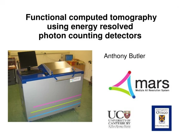
Test Setup • Simple test - drop Medipix2 chip into LN2 • Mounted on ceramic header used for 350C tests • Attached to brass heat sink and copper cold finger • Accurate diode thermometer glued to header
Feasibility Test at DRS • Used existing 8x8 APD array mounted on fan-out header • Wirebonded 8 APD outputs to 8 Medipix2 input pads • Hybrid assembly mounted on larger header • Large header mounted in test dewar • Expect higher amplifier noise due to increased capacitance • Use IR photodiode as photon light source to input light pulses • Use photon-transfer curve to characterize gain and noise
Medipix2 Wirebonds APD array Medipix2 and APD array
Future work • Start/continue feasibility tests • Quantify noise, gain and threshold sensitivity • Extrapolate results to realistic APD mounting • Investigate APD fabrication techniques onto Medipix wafer • Model/simulate APD pixel to match Medipix • Seek funding to pursue full chip fabrication
Summary If successful, this effort could lead to a sensor with: • HgCdTe QE (c < 4.3 m) • Large arrays (512 x n*256) • Zero readout noise • kHz frame rates or higher • Electronic shutter Which should prove very useful for many niche applications with low background in the IR