GMT-P1 Digital Indicator
GMT-P1 digital indicator is specially designed for weight transmitting in industrialfields. Support PROFINET and Ethernet IP, GMT-P1 digital indicator is a small weight display specially designed and produced for the occasion of weight transmit industrial. The indicator features compact size, stable performance, and simple operation. Can be widely used in: cement mixing and asphalt mixture equipment, metallurgical blast furnace, converter, and chemical industry, feed weight control and other occasions.


GMT-P1 Digital Indicator
E N D
Presentation Transcript
Model no.: GMT-P1 —PN/EIP User’s Manual 110611010012 V30.02.01
©2021, Shenzhen General Measure Technology Co., Ltd reserves all copyright. Without permission from Shenzhen General Measure Technology Co., Ltd., Any corporations or person must not copy, spread, record or translate into other language by any forms. Our company reserved the right to update user’s manual without additional notice to customers by reason of update, so please visit our website or contact with our service person to get update information. Website: http://www.gmweighing.com Product Performance Standards: GB/T 7724—2008
CONTENTS 1 General Description..................................................................................................................1 1.1 Functions and Characteristics.................................................................................1 1.2 Front Panel..................................................................................................................2 1.3 Rear Panel...................................................................................................................4 1.4 Technical Specifications............................................................................................4 1.4.3 Digital:............................................................................................................5 2 Installation and Wiring..............................................................................................................6 2.1 Connection of Power Supply...................................................................................6 2.2 Connection of Load Cell........................................................................................... 6 2.2.1 6 wires connection......................................................................................7 2.3 I/O terminals................................................................................................................8 2.4 Profinet/Ethernet IP connection..............................................................................9 3 Calibration.................................................................................................................................11 3.1 Instruction...................................................................................................................11 3.2 Flow Chart of Calibration........................................................................................12 3.3 Millivolt Value Display..............................................................................................17 3.4 Calibration with Weights.........................................................................................18 3.5 No weight calibration...............................................................................................18 3.5.1 No weight zero Calibration......................................................................18 3.5.2 No weight gain Calibration......................................................................19 Historical gain calibration...................................................................................20 Sensitivity and gain calibration range.............................................................21
3.6 Calibration Switch for Communication Interface...............................................22 3.7 Explanation for Calibration Parameters..............................................................22 4 Working Parameters Setting.................................................................................................24 4.1 Flow Chart of Working Parameters Setting........................................................24 4.2 Parameter Setting Method.....................................................................................25 4.3 Descriptions of Operation Parameters................................................................26 4.4 Set point parameters...............................................................................................30 5 I/O Definition.............................................................................................................................33 5.1 I/O Definition..............................................................................................................33 5.2 I/O testing...................................................................................................................36 6 Communication........................................................................................................................38 6.1 PROFINET Communication...................................................................................38 6.1.1 I/O Status....................................................................................................38 6.1.2 Indicator Description file GSD................................................................56 6.1.3 Profinet master configuration GMT-P1.................................................56 6.2 Ethernet-IP communication....................................................................................68 6.2.1 IO status......................................................................................................68 6.2.2 Device description file ESD....................................................................74 7 Password Input and Setting Reset......................................................................................78 7.1 Password Input.........................................................................................................78 7.2 Password Setting.....................................................................................................78 7.3 Factory Reset............................................................................................................80 8 Display Testing.........................................................................................................................82
9 Errors and Alarm Messages................................................................................................. 83 10. Indicator model user-defined function.............................................................................84 11 Dimension of Indicator......................................................................................................... 85
GMT-P1 Digital Indicator 1 General Description GMT-P1 digital indicator is specially designed for weight transmitting in industrial fields. Support PROFINET and Ethernet IP, GMT-P1 digital indicator is a small weight display which is specially designed and produced for the occasion of weight transmit industrial. The indicator has the features of compact size, stable performance, simple operation. Can be widely used in: cement mixing and asphalt mixture equipment, metallurgical blast furnace, converter and chemical industry, feed weight control and other occasions. 1.1 Functions and Characteristics Small volume, unique design, easy operation Applicable to all kinds of resistance strain gauge bridge load cell Front panel numerical calibration Multilevel of digital filter Automatic zero -tracking Automatically zero when powered on PROFINET fieldbus interface Support Ethernet IP communication, can access Ethernet IP network Weight display can be remotely calibrated (remote calibration ON/OFF turned on) 1
GMT-P1 Digital Indicator 1.2 Front Panel Main Display: 6 digits, for displaying weight and the information of parameters. Status Indicator Lamp: ZERO: Light on when present weight is within 0±1/4d. the state of I10. STAB: Light on when changes of weight values are within the range of motion detecting during motion detecting time. NET: Light on when indicator is in net weight status. Keypad: 2
GMT-P1 Digital Indicator : Zero/Esc, exit from current operation or go previous. Long press the ZERO button to calibrate the ZERO point function. The calibration range of the ZERO point in the main interface is limited by the ZERO clearing range, and cannot exceed the zeroing range, but it is not limited by : Scroll optional values of parameter and to make flashing digit increase 1 while data inputting. Long press Tare key will proceed data transmission, and the light will be flicker, and update the F1.8 parameters : Function selecting key, make flashing position move to the right digit when data inputting. : Confirming Key. Confirm setting parameters or calibration and input data. Note: Under the status of gross weight, user could remove tare by pressing OPTION key, and if press Esc key in net weight mode, it will add tare weight, while it is zeroing under the status of net weight. It will show net weight value after tare, meanwhile the NET light is on. 3
GMT-P1 Digital Indicator 1.3 Rear Panel PN/EIP indicator, light on when bus communication 1.4 Technical Specifications 1.4.1 Common: Power supply: DC24V±5% Working temperature: -10~ Max humidity: 90%R.H without dew ~40℃ ℃ 4
GMT-P1 Digital Indicator Power consumption: About 10W Dimension: 105×89×57( (mm) ) 1.4.2 Analog: Load cell power: DC5V Input impedance: 10MΩ Zero steady range: 0.00~ Input sensitivity: 0.01uV/d Input range: 0.00~ Transfer mode: Sigma - Delta A/D conversion speed: 30, 60, 120, 240, 480, 960 times/sec Non-linearity: 0.01% F.S Gain drift: 10PPM/℃ ℃ Display Precision: 1,000,000d 1.4.3 Digital: Weight display: 6 digits red high-brightness LED Minus display: “-” Overload display: “OFL” Decimal point: 5 kinds (optional) Function keys: 4 keys soniferous keypad 200mA( (MAX) ) ~12mV(Load cell 3mV/V) ~15mV(Load cell 3mV/V) 5
GMT-P1 Digital Indicator 2 Installation and Wiring 2.1 Connection of Power Supply GMT-P1 digital indicator connects DC24V power supply as follows: Power supply connection 2.2 Connection of Load Cell GMT-P1 digital indicator connects bridge type resistance strain gauge load cells by 6 wires or 4 wires as follows. When you use 4-wired load cells, you must bridge the SN+ with EX+ and bridge the SN- with EX-. The signal definition of each port of the load cell connector is as follows: EX+: Excitation+ EX-: Excitation- SN+: Sense+ SN-: Sense- SIG+: Signal+ SIG-: Signal- 6
GMT-P1 Digital Indicator 6 wires EX+ SN+ EX- SN- SIG+ SIG- Shield 4 wires EX+ EX- SIG+ SIG- Shield 2.2.1 6 wires connection Note: 1. As load cell output sensitive analog signal, please use shield cable to separate with other cables, especially AC power. 2. 4 wires connection is suitable for short distance and stable temperature or low precision field, otherwise use 6 wires connection. 3. For more load cells parallel connection, their sensitivity (mV/V) should be same. 7
GMT-P1 Digital Indicator 2.3 I/O terminals I/O tolerant definition as follows: Output OUT1 Stable OUT2 OFL Input Reset all IN1 Indicator input terminal connection: Indicator input terminal connection: 8
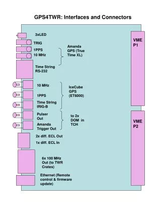
GMT-P1 Digital Indicator 2.4 Profinet/Ethernet IP connection GMT-P1 supports PROFINET and Ethernet IP communication, and provides two Ethernet ports. With the choice of two network ports, the network port has built-in switch, which is used to realize the cascading between multiple devices. 9
GMT-P1 Digital Indicator Internal communication indicator: Hardware connection is normal, the internal communication indicator is ON. Connector indicator: cable connection is normal, connection light is flashing 10
GMT-P1 Digital Indicator 3 Calibration 3.1 Instruction (1)Calibration procedure must be executed when a GMT-P1 indicator is put in use at the first time, the preset parameters may no longer meet the user’s needs, and any part of the weighing system was changed. Position of decimal point, minimum division, maximum capacity, zero, and gain can be set and confirmed through calibration. ( 2 ) If you want to set only one parameter, please press to save parameter’s value and then press to exit. (3)Please see section 3.7 for parameters’ instruction. 11
GMT-P1 Digital Indicator (4)Please record each value in the blank table in section 3.4 during calibration for the emergency use in future. (5)See chapter 9 for error alarm message that may be displayed during calibration. 3.2 Flow Chart of Calibration 1. Under this status, press (twice), indicator will display CAL, then Normal Status press to enter password input. 2. After password is input, the indicator will display CALON for one second, then go to Password input next step. 12
GMT-P1 Digital Indicator 3. Press to select a desired value for decimal point among 0, 0.00, 0.000 and 0.0, 0.0000, and then Decimal point press If there’s no need to change the value, to save it and enter next step. press directly to enter next step. 4. Press division among 1,2, 5,10,20 and 50, and then to save it and enter next step. If there’s no need to change the Min,division, to select a desired value for min. Min. divistion then press directly to enter next step. 5. Input max. capacity(≤min. division×1000000), press display interface. If there’s no need to change the max. capacity to save it and enter Millivolt value Max. capacity value, then press Millivolt display interface. directly to enter 13
GMT-P1 Digital Indicator 6. Under this status, press calibration. Display value near the output value in millivolt between SIG+/SIG- of load cell. See section 3.3 for details about this function. to enter zero Millivolt value display 7.Unloaded scale first, when STAB lamp is on, press If to finish zero calibration. no need there’s to calibrate zero, press directly to enter gain calibration. Zero calibration 14
GMT-P1 Digital Indicator 8. The process of gain calibration is as follows. If there’s no need to do gain calibration, press directly to enter serial ports calibration switch setting. 15
GMT-P1 Digital Indicator 9. Press to enter remote calibration ON/OFF, press to choose the switch position, press to set password。If don’t need to set switch position, then press setting. to enter password 10. See section 7.2 for reference to set password. If there’s no need to set password, press status. directly to go back to normal 16
GMT-P1 Digital Indicator 3.3 Millivolt Value Display This function is mainly used for system test, position-error test for weighing mechanism and linearity test for load cell. 1. System Test (1) If display data changes with loaded weight changes, it shows that connection of load cell is correct and weighing mechanism works well. (2)If display value is OFL (or –OFL), it means that loaded weight on load cells is too large (or too small). Please unload the weight (or load more), if display value is still OFL (or –OFL), the possible reasons are as follows: a. There is something wrong with weighing mechanism, please check and clear. b. The connection of load cell is incorrect, please check and clear. c. Load cells may be damaged, please replace. 2. Position-error Test for Weighing Mechanism Load a same weight on each corner of weighing mechanism and record displayed millivolt value respectively. If differences among these values are obvious, please adjust weighing mechanism. 3. Linearity Test for Load Cell Load same weight for several times, and record displayed value every time. If one or two values are obviously much larger or smaller than any others, it means that the linearity of load cell is bad. *NOTE: Press to zero every time before weight is loaded. 17
GMT-P1 Digital Indicator 3.4 Calibration with Weights In Chapter 3.2, steps 7 and 8 in the calibration flow chart are operation instructions of calibration zero point and calibration gain with weights During calibration with weight,please record the zero millivolt value, gain millivolt value and the loaded weight value in the blank table below. If it is not convenient to load a weight to calibrate, these values can be used for calibration without weights. Zero millivolt value(mV) value(mV) 1 2 3 4 5 3.5 No weight calibration Gain millivolt Loaded Weight Date Remarks 3.5.1 No weight zero Calibration When the mechanism is calibrated with weights, the millivolt value corresponding to the empty balance should be recorded. Zero calibration is accomplished by manually entering historical values. 18
GMT-P1 Digital Indicator 3.5.2 No weight gain Calibration There are two methods for weighting - free calibration gain 1) Historical calibration: Gain calibration by entering historical record values 2)Theoretical calibration: Calibrate through sensor sensitivity and maximum range value of input mechanism (the sum of the average value of input sensitivity and 19
GMT-P1 Digital Indicator maximum range when multiple sensors are connected) Historical gain calibration 1) In gain calibration interface, press , and the interface displays 1. Press millivolt value. to enter the manual gain millivolt input interface and enter the historical 20
GMT-P1 Digital Indicator 2) Press corresponding to the millivolt number. save to enter the weight input interface and enter the weight value 3) Press switch. Sensitivity and gain calibration range save to complete gain calibration and enter the serial port calibration 21
GMT-P1 Digital Indicator 1) In gain calibration interface, press twice interface for manual input of sensor sensitivity and input the sensitivity of the actual sensor. to enter and choose "2" press enter 2) Press , enter the maximum range input interface and input sensor range. 3) Press , complete gain calibration and enter serial port calibration switch. 3.6 Calibration Switch for Communication Interface When calibrate the transmitter through serial port( Rs,SP1 or Modbus), must set to “ON” status for the calibration switch for communication interface. 3.7 Explanation for Calibration Parameters Symbol Parameter Types Value of parameter Default Pt 1d Decimal Point Min. Division 5 6 0 0.0 1 0.00 5 0.000 10 0.0000 50 0 1 2 20 CP ≤Min. Division×100000 10000 Max. Capacity t Millivolt Value 22
GMT-P1 Digital Indicator o Zero C Gain Switch for Calibration via serial interface Password Setting SIOCAL OFF PASS 000000 Log Table for Calibration Parameters Parameter Decimal Point Min. Division Max. Capacity Load cell sensitivity Password Calibrated Value Date Remarks 23
GMT-P1 Digital Indicator 4 Working Parameters Setting 4.1 Flow Chart of Working Parameters Setting Normal Status If F4.1(Password Switch) is ON, you SET UP should input password first. F1 F1.1 F1.8 1 .Use to select between the same level. Switch from display F1 to F2, press . 24
GMT-P1 Digital Indicator F2 F2.1 F2.7 2 .Press return back to previous menu. to enter into sub-selection, press to When it displays F2,press to enter into F2.1. F3 F3.1 F3.2 F4 F4.1 4.2 Parameter Setting Method GMT-P1 has 2 kinds of working parameters: Selection type and data type. For 25
GMT-P1 Digital Indicator selection type parameters, press to choose. For data type parameter in parameter interface, press to choose digit position, press to choose value. Selection: F1.1 OFF ON F1.1 Enter setting status Change OFF to ON Confirm the change Data: 60 50 50 F1.4 Enter setting status Move the flashing from 0 to 5 Adjust value Confirm chage F1.4 4.3 Descriptions of Operation Parameters Code Default Description 26
GMT-P1 Digital Indicator F1 Null The first major term of working parameter. Switch for Auto-Zeroing when power-on, OFF: disabled ON: enabled Zero-tracking Range(0~9d optional). This parameter is for automatic calibration, disabled when is set ”0”. Motion Detecting Range(0~9d optional) It is stable if the change is within range. Zeroing Range(00%~99% of Maximum capacity) F1.1 OFF F1.2 0 F1.3 0 F1.4 50 F1.5 5 Digital filtering parameter: (0-9 as optional) 0: without filtering 9: strongest digital filtering VF-Filter 0: without filtering 9: strongest digital filtering(0-9 as optional) A/D conversion rate: 120,480,960,15,30,60 as optional 0 : NET indicating net weight ; 1 : NET indicating communication Parameter remote set ON/OFF If this parameter set to ON,Then work parameters and F1.6 0 F1.7 F1.8 0 0 F1.9 OFF 27
GMT-P1 Digital Indicator part of calibration parameters can be modified through the master station. If this parameter set to OFF, the modified parameters on the primary site do not take effect. GSD1/ EDS1 PN Parameters: GSD1 (standard),GSD2(compact) EIP Parameters: EDS1 (standard), F1.10 EDS2(compact) PN Parameters: The main interface LED represents:Heartbeat or Tare alarm。OFF:Tare alarm. ON:Heartbeat F1.11 ON F2 F2.1 Null 01 The second major term of working parameter. Scale no., indicator no. Baud rate of serial port:1200 / 2400 / 4800 / 9600 / 19200 / 38400 / 57600 F2.2 38400 F2.3 Modbus-R Serial ports communication mode: Modbus-RTU: r-Cont:SP1 continuous mode; r-SP1: SP1 command mode; tt:TOLEDOcontinuous mode; Cb920: :Cb920 continuous mode。 :MODBUS RTU mode; TU ; ; 。 28
GMT-P1 Digital Indicator rE-Cont:rE continuous mode; rE- rEAd:rEcommand mode; ; ; Data format: 7-E-1:7 data bit,even parity check,1 stop bit; 7-O-1:7data bit,odd parity check,1 stop bit; 8-E-1:8 data bit,even parity check,1 stop bit; 8-O-1:8 data bit,odd parity check,1 stop bit; 8-n-1:8 data bits,no parity check,1 stop bit; 8-n-2:8 data bits,no parity check,2 stop bits; F2.4 8-E-1 MODBUS dual-byte register storage turn,Hi Lo: byte in the front, low byte at the back;Lo Hi: the front, high byte at the back :High HiLo F2.5 :Low byte in F2.6 Cont mode automatic sending time interval nONE tt(TOLEDO continuous mode)If send the checksum。 0:not send, 1:send. The third major term of working parameter. The first paragraph of IP, initial vale 192 F2.7 0 F3 F3.1 Null 0-255 29
GMT-P1 Digital Indicator F3.2 F3.3 F3.4 F3.5 F3.6 F4 F4.1 F4.2 F5 0-255 0-255 0-255 1-65534 The second paragraph of IP, initial vale 168 The third paragraph of IP, initial vale 1 The fourth paragraph of IP, initial vale 1 Modbus-TCP communication port no., initial value 502 Ethernet communication mode The fourth major term of working parameter. Parameters password setting switch. Parameters password setting:Valid when F4.1 is ON Parameter setting refer the 5thterm Weight correction factor K, weight correction factor K = Expected weight/current weight range: 0-9.99999 When the weight is calibrated (gain) or the calibration parameter is reset, the value changes to the default value of 1.00000 0:b Tcp;1:Cont Null OFF 000000 Null F5.1 1.00000 4.4 Set point parameters Code Default Description P1-P4 PX.1 Null OFF The first term of working parameters Change of state if need stable 30
GMT-P1 Digital Indicator Change of state minimum duration Condition of validity: 0:forbid; 1: < Less than; when the weight is less than Fx. 4, the output is valid, otherwise it's invalid 2:<= Less than or equal to; when the weight is less than or equal to Fx. 4, the output is valid; otherwise, it is invalid. 3:== Equal; when the weight is equal to Fx. 4, the output is valid; otherwise, it is invalid PX.2 0.0 PX.3 P1.3=1 P2.3=5 P3.3=0 P4.3=0 4:>=;Bigger than or equal to; when the weight is greater than Fx. 4, the output is valid, otherwise, it is invalid 5:> Bigger than; when the weight is greater than Fx. 4, the output is valid, otherwise, it is invalid 6:!= not equal to; when the weight is not equal to Fx. 4, the output is valid, otherwise, it is invalid 7:_<>_ Outside the interval, When the weight is less than FX.4 or more than Fx. 5, the output is valid, otherwise, it is invalid 8:=<__>= In the interval, when the weight is bigger than or 31
GMT-P1 Digital Indicator equal to Fx. 4 and less than or equal to Fx. 5, the output is valid, otherwise, it is invalid 9:external trigger. If it’s IO,do 1 state change for 1 trigger, if it’s command, then decide according to valid or invalid command. PX.4 0 Set value 1; 0 ~ 999999 can be set PX.5 0 Set value 2; 0 ~ 999999 can be set Set point has 4 major terms which are user defined. 32
GMT-P1 Digital Indicator 5 I/O Definition 5.1 I/O Definition In the main display interface, press 4 times to display iodEF in the indicator. In this interface, press to enter the interface of custom setting of I/O module. If the password ON/OFF of working parameter F4.1 is set as ON, the password of working parameter needs to be entered before entering the custom setting of I/O module. Operation steps of I/O module customization: After entering the interface of I/O module customization, 1) Press to modify the definition of OUT1 2) Press to select the meaning code of I/O module 3) Press to confirm and return to the OUT1 interface 33
GMT-P1 Digital Indicator 4) Press to define the next I/O module, then press to skip the current I/O module definition (keep the original definition) to set the next I/O module. The definition method is the same as the above three steps, which will not be repeated here. Press to exit when the setup is complete. Output/Input code table: Output Code Definition Description O0 None No definition O1 Stable Effective output in stable status. O2 Overflow Effective output when overflow. O3 Sp1 Effective output when set point 1 status output. O4 Sp2 Effective output when set point 2 status output. 34
GMT-P1 Digital Indicator O5 Sp3 Effective output when set point 3 status output. O6 Sp4 Effective output when set point 4 status output. Input Code Definition Description I0 None No definition I1 Zeroing Effective input for zeroing, pulse input signals If this signal is valid, Sp1 status will be regarded as invalid. Output valid state when comparision condition turns to invalid, and be effective again. I2 Sp1 If this signal is valid, Sp2 status will be regarded as invalid. Output valid state when comparision condition turns to invalid, and be effective again. I3 Sp2 If this signal is valid, Sp3 status will be regarded as invalid. Output valid state when comparision condition turns to invalid, and be effective again. I4 Sp3 35
GMT-P1 Digital Indicator If this signal is valid, Sp4 status will be regarded as invalid. Output valid state when comparision condition turns to invalid, and be effective again. I5 Sp4 I6 Reset all Reset all parameter value when this signal is valid. I7 Tare/Add tare Tare when the first valid signal. Add tare when second. I8 Tare Tare when the signal is valid. I9 Add tare Add tare when the signal is valid. IO calibration lock, when I10 is defined, cannot be calibrated if the input is invalid. I10 I/0 define 5.2 I/O testing Under weighing status, press (5 times), then display TESTio,press interface. enter into I/O testing Normal Status 36
GMT-P1 Digital Indicator Press OUT1 status flash, press OUT2 status flash. This interface shows:IN1 input valid, OUT1 output valid. 37
GMT-P1 Digital Indicator 6 Communication 6.1 PROFINET Communication GMT-P1 display has two PROFINET-IO bus connections, Port1 and Port2, and can be used as a PROFINET-IO slave station to connect to the PROFINET bus. IP address of indicator can be set and viewed in Setup working parameters F2.1~F2.4; MAC address in F2.5~F2.10 to view. 6.1.1 I/O Status GMT-P1 provides multi-byte, IO output in two modules, through which the master station can read and control the status of the weighing display. 6.1.1.1 GSD1 Module 1: Weight and status parameter (read register) Weight offset Parameter Data type Description Weight display DInt 0 Current display weight, integer Weight status marker D4-D15 Reserved Duint 4 D3:Weight marker 38
GMT-P1 Digital Indicator D2 : ZERO , ( weight is in 0+/-1/4d range) D1:Weight overflows bit D0:Weight stable marker Gross weight Gross weight ( signal integer) DInt 8 Net weight Net weight ( signal integer) DInt 12 Tare weight Tare weight ( signal integer) DInt 16 Current weight, floating-point type Gross weight, floating-point type Net weight, floating-point type Current weight Float 20 Gross weight Float 24 Net weight Float 28 Tare weight, floating-point type Tare weight Float 32 D5-D15 Reserved D3:Preset point 4 status area Preset point status area Word 36 39
GMT-P1 Digital Indicator D2:Preset point 3 status area D1:Preset point 2 status area D0:Preset point 1 status area The value of PN's communication heartbeat is always 1 after the connection is established, and the communication light is always on. After flashing the LED light, the communication light will blink at the frequency of 1Hz, and the value of communication heartbeat will also convert between 0 and 1 at the frequency of 1Hz Heartbeat communication Word 38 Module 2: Calibration parameter (read register) Weight offset Parameter Data type Description 40
GMT-P1 Digital Indicator Weight calibration Read Read absolute millivolts Read relative millivolts register 0 DWord Weight ZERO calibration 4 DWord Weight gain calibration No weight calibration Read Zero calibration millivolt Read gain calibration millivolt Read gain calibration weight No weight ZERO calibration 8 DWord No weight gain calibration voltage value No weight gain calibration weight 12 DWord 16 DWord Theoretical value calibration Load cell sensitivity 20 DWord Load cell sensitivity 41
GMT-P1 Digital Indicator Load cell full range Load cell full range 24 DWord used to correct the weight value factor 28 DWord Weight correction factor Custom read Reads the value of a specific address Write data return status 0: normal 1: register address is illegal 2: parameter error Write data return status 0: normal 1: register 32 DWord Modbus read out value 36 Word Modbus write status 38 Modbus read status Word 42
GMT-P1 Digital Indicator address is illegal 2: parameter error Module 3: Calibration parameter (write register) Weight offset Parameter Data type Description Weight calibration Write Write 1 to automatically calibrate zero Enter weight value register 0 DWord Weight ZERO calibration 4 DWord Weight gain calibration No weight calibration write Zero calibration millivolt write gain calibration millivolt No weight ZERO calibration 8 DWord No weight gain calibration voltage value 12 DWord 43
GMT-P1 Digital Indicator No weight gain calibration weight write gain calibration weight 16 DWord Theoretical value calibration Write load cell sensitivity Write load cell full range 20 DWord Load cell sensitivity Load cell full range 24 DWord used to correct the weight value factor 28 DWord Weight correction factor Function operation D15:I/O module D14:parameter reset D13:calibration reset 32 Duint Function operation 44
GMT-P1 Digital Indicator D12:all reset D4-D11 reserved D3:GS/NT D2:clear tare D1:tare D0:zero Self-define write Modbus write operate address Modbus write operate value Modbus read operate value Modbus write operate address Modbus write operate value Modbus read operate value 36 DWord 40 DWord 44 DWord 6.1.1.2 GSD2 Weight offset Parameter Data type Description 45