Download
1 / 62
620 likes | 647 Views
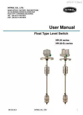
CW-15K standard weighing scale is a high speed, high precision and big range<br>industrial automatic weighing scale developed by our company to meet the changing<br>technological update.<br> The full touch screen makes the CW-15K weighing scale easy to operate, external<br>expansion of IO input and output and external serial port communication to achieve multipoint control, monitoring, and remote control of the product.<br>

E N D
Check weigher CW-15K User’s manual ( A p p l i c a b l e f o r M C G S + C 0 1 v e r s i o n ) 531701010030 Ver A1
Contents 1.Summary ............................................................................................. 1 Product Features ........................................................................... 1 1.1 1.1.1Mechanical part .................................................................. 2 1.1.2Electrical part ..................................................................... 2 Usage Notice ................................................................................ 2 1.2 1.2.1Precautions ........................................................................ 2 2. Product installation ................................................................... 3 Overall appearance ........................................................................ 3 2.1 Mechanical installation ................................................................... 4 2.2 Electrical installation ..................................................................... 4 2.3 Electrical interface ......................................................................... 6 2.4 Power supply power..................................................................... 10 2.5 3. Operation .................................................................................... 11 Operation summary ................................................................. 11 3.1 Limit removal ......................................................................... 11 3.2 Basic operation ....................................................................... 12 3.3 3.3.1Power-on operation .......................................................... 12 3.3.2Zero clear operation .......................................................... 14 3.3.3Start up operation ............................................................ 14 3.3.4Stop operation .................................................................. 14
3.3.5Power off operation .......................................................... 14 User login ............................................................................... 14 3.4 Product selection with New .................................................... 15 3.5 3.5.1Select product parameters ................................................ 15 3.5.2New product parameters ................................................... 16 3.5.3Modify product parameters................................................ 19 3.5.4Delete product parameters ................................................ 20 Calibration scale ..................................................................... 20 3.6 3.6.1The weight calibration scale .............................................. 21 3.6.2Dynamic calibration of scale .............................................. 21 4. Data viewing ............................................................................ 24 Check the result data .................................................................... 24 4.1 Statistics .................................................................................... 25 4.2 Alarm information ....................................................................... 25 4.3 Statistical graph .......................................................................... 26 4.4 5. Quantity of switches ............................................................... 27 I/O I/O testing ............................................................................ 27 5.1 6. Working parameters ................................................................ 32 Working parameter Settings .......................................................... 32 6.1 7.Communication .............................................................................. 37 Communication parameters ........................................................... 37 7.1
7.1.1Serial port communication ................................................. 39 7.1.2Network port communication ............................................. 39 7.1.3MAC address .................................................................... 40 The Modbus register communication address is defined ...................... 40 7.2 Print content ............................................................................. 46 7.3 Frequency converter parameter settings ..................................... 48 7.4 7.4.1Mitsubishi frequency converter parameter settings ............. 48 7.4.2Schneider frequency converter ATV320U07M2C parameter setting 50 7.4.3Schneider frequency converter ATV320U07M2C parameter setting 51 8. Program upgrade ..................................................................... 52 9.Size .................................................................................................. 53 Outline size drawing (unit: mm) ..................................................... 53 9.1 10. Equipment repair and maintenance ...................................... 54 Maintenance of motors ........................................................... 54 10.1 10.1.1Routine maintenance ........................................................ 54 10.1.2Regular maintenance ........................................................ 54 10.1.3Precautions ...................................................................... 54 Check the failure cause and treatment method of weight scale . 54 10.2 10.2.1No display on the touch screen .......................................... 54 10.2.2Data pulsation large, abnormal fluctuation ......................... 54
10.2.3The display is always zero ................................................. 55 10.2.4Abnormal data display....................................................... 55 10.2.5Busy alarm ....................................................................... 55 10.2.6Packaging error ................................................................ 55 10.2.7Continuous nonconformity alarm ....................................... 56 10.2.8Excess plugging time ........................................................ 56 10.2.9Below the minimum sampling time .................................... 56 10.2.10Super maximum sampling time ........................................ 56 10.2.11Overload motor load limit ................................................. 56 10.2.12Automatic zeroing failed .................................................. 56
Shenzhen General Measure Technology Co., Ltd.All rights reserved. Without the permission of Shenzhen Geman Technology Co., LTD., no unit or individual may copy, disseminate, transcribe or translate into other language versions in any form or by any means. Due to the continuous improvement and update of our products, we reserve the right to modify this manual at any time without prior notice.For this purpose, please visit our website frequently for timely information. The company's Web address http://www.gmweighing.com
CW-15K user’s manual 1.Summary CW-15K standard weighing scale is a high speed, high precision and big range industrial automatic weighing scale developed by our company to meet the changing technological update. The full touch screen makes the CW-15K weighing scale easy to operate, external expansion of IO input and output and external serial port communication to achieve multi- point control, monitoring and remote control of the product. 1.1 Product Features Product parameters; Model number CW-15K Power Supply AC220V±10%, 50/60Hz, 350W Weighing range 1 to 15kg Accuracy of weight inspection Plus or minus 5 g Weight checking speed 55 to 85 pieces/min Size of object to be measured Length: 100~600mm Width: 50~450mm Height: 50~500mm Conveyor belt speed 45 to 68 m/min Belt size 800mm*500mm Center distance of drum shaft 800mm Countertop height 750 (±50mm) (customizable) Operating temperature 0 to 40ºC Maximum humidity 90% R.H non-dew forming The instantaneous ultimate load shall not exceed 30kg Ultimate load Note;Scale stands are strictly prohibited from being used over the range. Note;Scale stands are strictly prohibited from being used over the range. 1
CW-15K user’s manual 1.1.1Mechanical part 1.Electric control box is small and movable, easy to install and operate on site. 2.The servo driver is used as the motor driving device to ensure the speed stability and adjustability in the process of weight checking. 3.Double photoelectric mode more accurately determine the object up and down the weighing platform, improve the accuracy and efficiency of weight detection. 4.The height adjustment range of the weighing table is larger, which is convenient for customers to choose and use. 5.The mechanical modular design makes transportation and maintenance more convenient, and the application adaptability stronger. 1.1.2Electrical part 1.Simple wiring, external only need to access the power cord;The internal use of different specifications pin plug terminal block, wiring is convenient and will not make mistakes. 2.Touch screen operation interface optimization, product parameter setting is simple and the main interface content is richer. 3.The three-color indicator shows qualified (green), out-of-tolerance (red), undertolerance (yellow), and the working state of the inspection weight is clear at a glance.Buzzer user can define the alarm mode. 4.The new algorithm is adopted in the process of weight inspection, and the high precision can be guaranteed in the process of high-speed weighing. 5.Optimize user login and logout function, without tedious operation and effectively prevent others from misoperation. 1.2Usage Notice 1.2.1Precautions 1.Do not perform mechanical or electrical maintenance while live, do not place tools on the scale, and do not perform welding operations on the scale. 2.The installation site must ensure the ground level, after installation through the foundation adjustment, ensure that the weighing table level, tilt does not exceed 0.5 degrees, away from the vibration source. 3.Make sure the equipment is safely grounded and there is no strong electricity or magnetic field interference nearby. 4.Do a good job of fire prevention, avoid direct sunlight to check the weighing table and relatively strong air flow (outdoor air, fan and air conditioning outlet is directly against the weighing table). 5.Should avoid squeezing, stepping on the scale platform, handling should first fixed scale, installed sensor limit to prevent damage to the sensor, prohibit the direct handling of the scale platform to move. 2
CW-15K user’s manual 2.Product installation 2.1Overall appearance The product appearance is shown in Figure 2-1 below. Figure 2-1 Overall appearance of the product Serial number Name Introduction indicator light More intuitive display of the weight inspection results, allowing the status of the results to be seen from a distance. 1 2 touch screen View display data and set product parameters Turn on/off the power supply of the weighing scale for inspection Knob switch 3 Emergency stop button Pressing this button in an emergency situation can immediately stop the motor from running 4 3
CW-15K user’s manual Electric control panel Control the weight inspection process and connect external devices 5 Photoelectric sensor Judge the weight table of the object up and down 6 7 reflector panel Photoelectric sensor beam reflection Weighing platform Weighing platform for the measured object 8 Timing belt protective cover Improving the safety of weighing scales during operation 9 10 Sensor limit Protect the sensor from external damage Prevent sliding and vibration of the weighing scale, and adjust the level of the weighing table. Peduncle 11 2.2 Mechanical installation Place the weighing scale at the installation place and remove the sensor protection device;Adjust the levelness of the weighing scale, and the inclination shall not exceed 0.5 degree;Fix the footing of the weighing scale, the stainless steel footing contacts the ground smoothly, and lock the screws of the footing to ensure the stability of the weighing scale. Adjust the distance between the check weighing platform and the front and rear end conveying mechanism is 9 ~ 11mm, and the check weighing platform shall not be in contact with other equipment.If the front and back end conveying mechanism is not equal to the height, it is necessary to add the oblique conveying mechanism on one side, and add the horizontal conveying mechanism connection on the side of the oblique mechanism (to leave a gap) to check the weight scale platform, to ensure that the check weight scale platform level and the height of the front and back end conveying mechanism. The electric control box can be arbitrarily installed on the left and right sides of the weighing scale to facilitate the operation of the production process. 2.3 Electrical installation The power supply is inserted into the three-hole socket with ground or connected to the power supply equipment such as the electric gas cabinet according to the line mark. 1.Any wiring and disconnecting operation can only be carried out after power off. After the operation is completed, check before power on. 2.The serial port is fixed to RS485 communication, where the 485(A) pair should be connected to 485(A) or 485(+), and the 485(B) pair should be connected to 485(B) or 4
CW-15K user’s manual 485(-). 3.The switching quantity input point is valid at low level (DC0V) and does not allow access to high voltage or alternating current. 4.Switching quantity output point access relay coil for intermediate control, so the other end of the relay can access DC or AC power supply switching quantity. Figure 2-2 Control panel of weighing scale Serial number Function 1 Touch screen communication jack 2 External custom outlet OUT1-OUT4 3 External custom output relay K1-K8 5
CW-15K user’s manual 4 Detect the photoelectric sensor wiring terminals 5 Alarm light wiring terminals 6 Custom input ports 1-6 externally 7 Sensor terminal 8 External RS-485 communication jack 9 External TCP/IP communication network port 10 Inverter communication jack 11 External USB data interface 12 24V power terminal 13 Reset key 14 Communication status indicator 15 Output relay status indicator light 2.4Electrical interface Photoelectric sensor (already wired at factory) : Photoelectric sensor (already wired at factory) : E24V: photoelectric sensor DC24V+. E0V: photoelectric sensor DC24V-. E1: Signal input of photoelectric sensor for loading of weighing scale. E2: Check the output photoelectric sensor signal input of the weight balance. Alarm light (has been connected when leaving the factory) : Alarm light (has been connected when leaving the factory) : L24V: Alarm light DC24V+, maximum output power 2VA. L1: Buzzer. L2: When the detection result is out of tolerance, the low output is valid until the next check begins. L3: When the test result is qualified, the low output is valid until the next check begins. L4: When the detection result is inferior, the low level output is effective until the next check starts. 6
CW-15K user’s manual Input (function can be customized, onsite connection according to actual Input (function can be customized, onsite connection according to actual demand) : demand) : DI1: running input. In the stopped state, the input is valid and the system enters the running state. DI2: Stop input. In the running state, the input is valid and the system enters the stop state. DI3: clear the alarm. When the system generates an alarm, change the input to be effective and the alarm will be cleared. DI4: out-of-tolerance elimination is completed. When the input is valid, the output of out-of-tolerance elimination is invalid. DI5: Undererror culling is complete, undererror culling output is invalid when this input is valid. DI6: continuous packet detection. This input signal is given by the photoelectric sensor installed on the front conveyor line of the weighing scale and used in conjunction with the busy stop output to control the start and stop of the front conveyor line of the weighing scale. When there is an object being detected on the weighing platform and the signal is effective, the busy stop output is effective. DI0V: switching quantity power supply DC24V-. DI24V: Switching quantity power supply DC24V+. 4 transistor outlet (function can be customized, on 4 transistor outlet (function can be customized, on- -site actual demand connection) : actual demand connection) : site according to the according to the DO1: No definition. DO2: undefined. DO3: undefined. DO4: undefined. DO0V: switching quantity supply power DC24V-. DO24V: switch quantity power supply DC24V+. DOCOM: switch quantity common end. Sensor (already co Sensor (already connected at factory) : nnected at factory) : EX+ : Power positive, SN+ : induction positive, EX- : power negative, SN- : induction negative, SG+ : signal positive, SG- : signal negative. 7
CW-15K user’s manual Motor speed control communication interface (RS485) : Motor speed control communication interface (RS485) : MT A: RS485 communication A. MT B: RS485 Communications B. MT G: RS485 Communication (GND). 8 8- -way relay outlet (function can be customized, on way relay outlet (function can be customized, on- -site connection according to actual demand) : to actual demand) : site connection according K1: defined as operation. When the system is in operation state, the relay output is closed, and K1A and K1B are switched on.Used to control the start and stop of frequency converter. K2: defined as stop. When the system is in the stopped state, the relay output closes and K2A and K2B are switched on.This definition is the factory default setting and can be modified according to the actual needs. K3: defined as out of tolerance elimination, the product test result is out of tolerance, and within the range of out of tolerance elimination duration, the relay output is closed,K3A,K3B switched on. K4: defined as undererror elimination, the product test result is undererror, and within the range of undererror elimination duration, the output of the relay is closed,K4A,K4B on. K5: defined as alarm. When the system gives an alarm, the output of the relay is closed, and K5A and K5B are switched on.This definition is the factory default setting, and can be modified according to the actual demand. K6: defined as batch completion, after the completion of the product test batch, the relay output is closed,K6A,K6B on.This definition is the factory default setting, and can be modified according to the actual demand. K7: defined as qualified indication, after the product test is qualified, the relay output is closed,K7A,K7B on.This definition is the factory default setting, and can be modified according to the actual demand. K8: defined as unqualified excluded. When unqualified occurs in the test result, the relay output is closed, and K8A and K8B are switched on.This definition is the factory default setting, and can be modified according to the actual demand. 8
CW-15K user’s manual User provide If need connect external relays, please connect in this way Figure 2-3 Schematic diagram of inlet and outlet connections Figure 2-4 Power supply and motor interface diagram Figure 2-4 shows the power supply and motor interface diagram, defined as follows: External power supply (already connected at factory) : External power supply (already connected at factory) : L: external AC power live wire. G: external AC power ground cable. N: neutral wire of external AC power supply. Frequency Frequency converter output power supply (factory has been connected) : converter output power supply (factory has been connected) : U: Corresponding to the U terminal connected to the motor. V: corresponds to the V terminal connected to the motor. 9
CW-15K user’s manual W: corresponds to connect the motor W terminal. Note: L, N and G are the external AC power supply, and U, V and W are the output power supply of the inverter to power the motor. These two groups of power supplies have been connected before delivery. If the frequency converter or motor needs to be reconnected in the subsequent use and maintenance process, please be sure to connect correctly according to the instructions, and remember not to connect it backwards, otherwise it will cause damage to the frequency converter. 2.5Power supply power AC220V±10%, 50/60Hz, 350W. 10
CW-15K user’s manual 3.Operation 3.1Operation summary Boot Technician w h New product c e h Set o Power Data Starting Figure 3-1 Procedure 3.2Limit removal Before use, it is necessary to remove the four limit protection devices. The position indicated by the arrow in Figure 3-2 is the limit position. Figure 3-2 limit position 1 11
CW-15K user’s manual Figure 3-3 limit position 2 Use a hexagonal open-ended wrench or adjustable wrench to remove the limit plates in Figure 3-2 and Figure 3-3. After removal, keep the screws safe for use during packaging and transportation. 3.3Basic operation The main interface of weight inspection is used for daily production, which is used to start and stop the weight inspection belt, enter the relevant parameter interface and display the basic information of the tested product and the weight inspection result. 3.3.1Power-on operation Turn on the power and turn the knob switch to the "1" position and the boat type switch to the O position.The touch screen on the electric cabinet displays the initialization interface.At the top of the interface are USB insert mark, check scale model and time display;The black display area is the name of the current production inspection product, the weight display area, the weight unit display area and the weight check scale status display area;In the middle is the current setting of weight checking speed, the current actual weight checking speed and the display statistics of weight checking results;At the bottom are the function keys of the operation of the weight check scale and the parameters related to the weight check. Correct time parameters can effectively help users check the production inspection results, relevant production parameter changes and alarm information, help to improve the production pass rate and production speed and reduce production consumption. The weight display area of the weighing scale displays the real-time weight value in the stopped state, and displays the weight test result in the running state until the next object is effective. 12
CW-15K user’s manual Figure 3-4 Power-on initialization interface Button and operation frame operation instructions (applicable to all operation interfaces of the device) : 1. parameters. Click this button to enter the interface of creating products and setting product 2. Click this button to enter the parameter setting interface. 3. Click this button to enter the data interface to view the relevant check data. 4. Click this button to clear zero. 5. Click this button for user management operations. 6. Click this button to start and stop the device. 7. Click this type of action box to modify the value of this item. 8. Click the action box to modify the value of this item. 9. Click this type of action box to select Settings for this definition. 10. Click this type of action box to perform the corresponding operation. 13
CW-15K user’s manual 11. Settings. Click this type of action box to open and close the corresponding function 3.3.2Zero clear operation If the touch screen displays the real-time weight value of the weighing scale in the stopped state is not zero (zero indicates the off state), click "Clear zero" to clear the weighing platform, so that the real-time weight value is displayed as zero, and then the zero indicates the on state.(It can be operated only in the stopped state). If the weight check scale shows that the weight is unchanged, the stable identifier bit is on; otherwise, the stable identifier bit is off (the stable identifier bit is only related to the weight state, and has nothing to do with the operation of the weighing scale and the size of the weight value). 3.3.3Start up operation Click "Start" on the touch screen to start the weight checking scale, and the weight checking motor drives the weight checking belt to rotate. At this time, the operation label on the touch screen is "Running", and the weight checking operation can start. 3.3.4Stop operation Click "Stop" on the touch screen to stop the weight inspection belt and end the weight inspection process. At this time, the operation label on the touch screen is "Stopped". 3.3.5Power off operation Turn knob switch to "0" position, touch screen off, disconnect power.The above operations can only be performed when there is no weight product on the weighing scale. 3.4User login password login box, select the user to enter the corresponding password and click "Confirm" to log in.The initial passwords of the operator and administrator are written in the user description. Under the touch screen initial interface, click "Product" or "Settings" to pop up the 14
CW-15K user’s manual Figure 3-5 Password input box 3.5Product selection with New Figure 3-6 Product list 3.5.1Select product parameters Click "Product" under the main interface to enter the product list interface. First, click the product to be checked in the product list, then click "Select Product" to select the product, click "Exit" to go to the main interface and click "Start" to check the product. 15
CW-15K user’s manual After the product is successfully selected, the current number will be displayed as the number of the selected product in the upper right corner of the product list page. The new product number cannot be selected during the operation of the weight check scale;By default, the product number selected by the weighing scale before exit (stop operation or the weighing scale power off). 3.5.2New product parameters On the product list page, click "Add Product" to jump to the "Product Parameters" interface to add a new product parameter. The new product number will be added to the existing product in sequence. You do not need to select the product number.For details, refer to "Operation Instructions on Buttons and Operation Frames" in Section 3.3.2. ★ The new product number cannot be added during the operation of the weight check scale;The newly added product parameter values are the default initial values of the system, which need to be set according to the actual product parameters and production requirements. Figure 3-7 Product parameters screen Example Description of product parameters: Name Instructions Product number Number of the product under inspection Speed of weight inspection The speed at which the current weight checking device detects the product 16
CW-15K user’s manual Product name Name of the product under inspection Belt speed Weigh the speed at which the belt is running Standard weight The standard weight of the product to be checked In the process of weight inspection, if the weighing value is greater than the target value + the upper limit value, it will be judged as out of tolerance Upper limit In the process of weight inspection, if the weighing value is less than the target value-lower limit value, it will be judged as undererror Lower limit value Tare weight The weight of the item's outer packaging Qualified culling distance The distance traveled by the product from the end of the scale to the start of the qualified culling mechanism Duration of qualified culling The duration of the qualifying cull mechanism's action Out-of-tolerance culling distance The distance traveled by the product from the end of the scale to the start of the offset removal mechanism Underweight culling distance The distance traveled by the product from the end of the scale to the start of the underbalance removal mechanism The out-of-tolerance culling action time The duration of the kill mechanism's action Undershoot culling action time The duration of the underkill operation Unqualified culling distance The distance traveled from the end of the scale to the nonconforming product after the start of the removal mechanism The time of the unqualified culling action The continuous action time of the rejection mechanism for nonconforming products (including out-of-error + undererror) Standard no correction is 1000. Correction factor =1000+(actual weight - test weight result)/ min indexing. That is, if the weight test result is light, the correction factor is the number greater than 1000, if the weight test result is heavy, the correction factor is the number less than 1000 Correction factor 17
CW-15K user’s manual Total lot Total number of pieces of heavy product inspected Qualified batches Number of eligible batches of products Sampling starting percentage The sampling data to this percentage is discarded after the object is placed on the scale Percentage used for sampling Data that is consistently used as a percentage from the start of sampling is used to calculate the weight check result Dynamic zeroing filter grade Filtering parameters in the weighing process Dynamic clearing stability range When the belt is running, within the stability determination time, the weight variation range is judged to be stable within this setting value, and only when it is stable can dynamic zeroing be allowed Dynamic zeroing and stabilizing time When the belt is running, within this setting value, the range of weight variation is judged as the stability of the scale platform within the range of dynamic zero clearance stability. Only when the stability allows the dynamic zero clearance Maximum sampling time Maximum sampling time during weighing When servo control is carried out, the average value of the set number of products is compared with the user's set value, and the difference between them is used as the basis of control.When it is 0, there is no need to fill the servo function Average feeding times Servo pulse frequency The pulse frequency value of the servo motor Number of product delays Equivalent to the number of objects from the charging machine to the photoelectric switch of the weighing scale.Also refers to the number of products passed before the next correction Servo charging sensitivity This setting is the adjusted weight corresponding to each correction pulse Servo target value Equivalent to the target value of package inspection weight Exclusion of servo upper limit When the weight is higher than this value, it does not participate in the average calculation and will generate an alarm 18
CW-15K user’s manual Exclude servo lower limit When the weight is below this value, it does not participate in the average calculation and will generate an alarm If the absolute weight error is less than this, no correction is made Servo dead zone Maximum servo modulation Means the maximum allowable modulation correction Exclude servo upper limit alarm stop Exclude the servo upper limit alarm to stop Exclude the servo lower limit alarm to stop Exclude the servo lower limit alarm to stop Failure to correct alarm stop in time Failure to correct alarm stop in time 3.5.3Modify product parameters On the Product list page, select the product whose parameters you want to modify from the product list and click "Product Parameters" to enter the product parameters interface to modify the selected product parameters (the newly added product directly jumps to the product parameters interface). The standard weight refers to the weight of the product to be checked, and the upper and lower limit is the allowable deviation value of qualified product;If it is not necessary to calculate the packaging weight of the product, the outer packaging weight of the product can be written into the tare weight column, and the net weight should be filled in the standard weight column. The product number is automatically generated by the system;The linear speed of the belt is calculated from the detection speed, and changes with the change of the detection speed. It cannot be filled in (the linear speed of the belt should be consistent with the linear speed of the front and rear end conveying mechanism). The compensation weight difference value is calculated by dynamic calibration. Under normal circumstances, manual change is prohibited to prevent deviation between the product weight and the actual weight. When filling in the product parameters, attention should be paid to its value range. Generally, if it is lower than the lower limit of the parameter range, the parameter value will remain unchanged; if it is higher than the upper limit of the parameter range, the upper limit of the parameter range will be written by default. The definition of weight checking speed, belt speed and correction coefficient is described in detail on the help interface of product parameters. If necessary, you can click "Help" to view. 19
CW-15K user’s manual 3.5.4Delete product parameters On the product list page, select the product to be deleted and click "Delete Product" to delete the product. After deleting the product, the following product parameters will move forward in order, and the product number will move forward.The product cannot be deleted during the operation of the weight check scale;In order to prevent product parameters from being incorrectly deleted, the product name should be set reasonably when setting product parameters. 3.6Calibration scale In order to ensure the correct weight of the weighing scale and the linearity of the weight change, each weighing scale needs to carry out weight calibration and dynamic calibration.For specific operation methods, please refer to "Operation Instructions on Buttons and Operation Frames" in section 3.3.2. Figure 3-11 shows an example of the weight calibration interface Description of static calibration parameters: Name Instructions Calibrate the empty scale table Eliminate external interference, the scale table at zero and stable, can be clicked Calibrate the scale weight Enter the weight of the calibration weight 20
CW-15K user’s manual The weight calibration scale Put the weight on and after entering the weight of the weight, click Current voltage value The current voltage value of the sensor Empty scale voltage value The voltage value of the sensor when the top of the scale is emptied Weight voltage value The voltage value of the sensor after placing the weight 3.6.1The weight calibration scale In the setting page, click "Static calibration" to enter the interface of weight calibration, follow the steps on the touch screen to calibrate the scale, and click "Exit" to return to the main interface after the calibration is completed.For specific operation methods, please refer to "Operation Instructions on Buttons and Operation Frames" in Section 3.3.2. During calibration, ensure that the weighing scale is in the stopped state; otherwise, the interface of the weighing scale cannot be entered;Calibration should ensure that there is no item on the weighing platform, no vibration on the weighing platform, and no relatively strong air flow around the weighing scale. When the weighing platform is empty, ensure that the weighing platform is at zero position and stable. Otherwise, please eliminate interference and click "Calibrate the weighing platform". The second step can only be carried out when the touch screen indicator is 0 and the stability sign is lit. When placing the weight, try to avoid the weight hitting the surface of the weighing platform. Enter the correct weight into the weight box of the weighing platform, otherwise it will lead to inaccurate calibration scale or calibration failure (the weight of the weighing platform should be greater than the product weight and not exceed the maximum range of the weighing scale). If the calibration fails, please check whether the scale is stable and whether the sensor is interfered by the outside world or whether the scale is in contact with other equipment, and re-calibrate after troubleshooting. 3.6.2Dynamic calibration of scale On the product page, click "Dynamic calibration" to enter the dynamic calibration interface, and perform dynamic calibration according to the text prompts. When completed, relevant parameters will be automatically calculated and generated and product parameters will be written.Click "Exit" to return to the main interface after completion of calibration.For details, please refer to Section 3.3.2 "Operation Instructions for Buttons and Operation Frames". 21
CW-15K user’s manual Figure 3-12 Dynamic calibration screen example Description of dynamic calibration parameters: Name Instructions Clear the current weight value to zero Zeroing Stop the belt running and put the test material on after the static weight value shown Get the weight Dynamic calibration times The number of repeated runs of dynamic calibration. The default is ten, and no less than five are recommended The belt will run, and after the statically weighed object has passed, it should be moved back to the front stage, repeatedly running dynamically, and the controller will automatically record the dynamic weight. General dynamic calibration ten times, the number of dynamic calibration to check the weight scale will automatically stop Start up The maximum value of the weight check result during dynamic calibration Maximum weight During dynamic calibration, the average weight of each check will be updated after the number of dynamic calibration is completed Average weight 22
CW-15K user’s manual The standard value is 1000. After the number of dynamic calibration is completed, the controller will automatically calculate this value according to the dynamic result and static weight. Correction factor If it is not convenient for dynamic calibration, you need to enter this value manually, which can be set in the product parameter interface, and fill in the size of the value refer to the method in the dynamic calibration parameter help interface Calibration must ensure that the check scale in the stopped state, otherwise can not enter the dynamic calibration interface;When calibrating, ensure that there is no item on the scale, no vibration on the scale, and no relatively strong air flow around the scale. When the weighing platform is empty, it should be ensured that the weighing platform is at zero position and stable, otherwise, please eliminate external interference and carry out "zero clearing" operation. When placing the product, the product should avoid hitting the surface of the weighing platform. Only after the weight is stable can you click "Obtain static weight";If the product has a gross weight value, please set the gross weight value first before dynamic calibration. The default value of learning times is 10. If the learning result is not accurate, you can increase the learning times appropriately.If the production requirement is not high, the learning times can be appropriately reduced to improve the learning speed;External interference should be avoided in the learning process, and the system will automatically save the learning results and display them after the completion of learning. The change of product detection speed requires dynamic calibration again. The principle of dynamic calibration, attention to implementation and alternative methods are introduced in detail in the interface of dynamic calibration parameter help. If necessary, you can click Help to view. 23
CW-15K user’s manual 4.Data viewing This check weight scale has data storage and query function, convenient for users to check the historical check weight data and event information.Under the main interface, click "Data" to enter the interface for viewing data (no permission is required for data interface). 4.1Check the result data In this interface, you can view the weight check time, weight check result and product code. When the weight check scale stops, insert the USB disk into the touch screen and click "Export data" to export all the weight check data to the USB disk;Click "Delete data" to delete all the current weight data;Click "Next page" or "Previous page" to review the duplicate data (in running state, only the duplicate data can be viewed, and the operation of "Export data" and "delete data" cannot be performed).For specific operation methods, please refer to "Operation Instructions on Buttons and Operation Frames" in Section 3.3.2. After testing a certain number of products, you can insert the USB flash drive to the touch screen to export the existing weight data, otherwise too much weight data will cause inconvenience to data query. Changing the production of the product and adding new products will not affect the query of the test result, delete the product, please first check out the test result and clear. Figure 4-1 Example of the weight check data page 24
CW-15K user’s manual 4.2Statistics Click "Statistics Data" to enter the check weight data statistics interface, which displays product distribution intuitively. Click "Print data" to print statistics information, click "Export data" to export statistics information to the USB disk inserted into the touch screen, click "Delete data" to clear statistics information.For specific operation methods, refer to "Operation Instructions on Buttons and Operation Frames" in Section 3.3.2. Statistics include out of tolerance, under tolerance, the cumulative number of inspection times of qualified products, weight, average value and probability distribution, etc. Before testing a new batch of product, the previous statistics should be cleared, otherwise the new product will accumulate on the original statistics and generate incorrect statistics. Figure 4-2 An example of the statistics page 4.3Alarm information Click "alarm record" to enter the interface for viewing alarm records, and you can view the alarm information in the process of weight inspection, including alarm serial number, alarm time, number and alarm content.For specific operation methods, please refer to "Operation Instructions of Button and Operation Frame" in Section 3.3.2. 25
CW-15K user’s manual Figure 4-3 Alarm information screen example 4.4Statistical graph Click "Statistical Chart" to enter the statistical chart interface to visually view the product weight distribution. Figure 4-4 Example of the statistical chart interface 26
CW-15K user’s manual 5.Quantity of switches 5.1I/O I/O testing Figure 5-1 I/O parameter screen Example 1 Figure 5-2 I/O parameter screen example 2 Click "Switch quantity" on the setting page to enter the IO test interface. The system provides 6 input terminals and 12 output terminals, which users can decide whether to use 27
CW-15K user’s manual according to production requirements.For specific operation methods, please refer to "Operation Instructions on Buttons and Operation Frames" in Section 3.3.2. IO test is to test whether the IO port is properly connected to the external device. During the test, click "Switch" after the output to output 1-8. If the corresponding relay coil is closed (red indicator light on the relay base) and the corresponding device is in action, the connection is normal and the output point of the weighing scale is valid; otherwise, please check whether the connection between the output point and the device is correct;Click the "switch" behind the three-color light, if the three-color indicator light is on, the connection is correct. The input test can be carried out by setting the low level signal (DC0V) at the input end. If the low level signal is effective at the corresponding input port, the test indicator box behind the corresponding input point ON the touch screen will light up and display "ON" (The photoelectric input can be blocked on the main interface when testing the photoelectric input, if the corresponding input and discharge marks are lit up, the photoelectric input is effective).The input and output signals can be defined by themselves. The default switching quantity is defined as follows: Enter the port number Output port number Definition Definition Relay - K1 DI1 Run Run Relay - K2 DI2 Stop Stop Relay - K3 DI3 Clear alarm Out-of-error culling Aberration culling complete Relay - K4 DI4 Undercount culling Relay - K5 DI5 Owe culling complete Alarm Relay - K6 DI6 Packet detection Number of batches completed I1 (incoming photoelectric sensor) Relay - K7 E1 Qualified indication I2 (discharge photoelectric sensor) Relay - K8 E2 Disqualified cull 28
CW-15K user’s manual DO 1 Undefined DO 2 Undefined DO 3 Undefined DO 4 Undefined L 1 O17 (Buzzer alarm output) O7 (alarm light out-of-tolerance indication, no relay) L 2 O10 (alarm light qualified indication, no relay) L 3 O6 (alarm light undererror indication, no relay) L 4 List of definable switching quantities: Enter switch quantity: Number Name Function description Undefined No function when this item is selected. I00 I00 Input photoelectric When the input is valid, it means that the input photoelectric sensor has sensed the measured object I01 I01 Output photoelectric When the input is valid, it means that the output photoelectric sensor has sensed the object under test I02 I02 When the input is valid, the device will boot into the running state Run I03 I03 Stop The device will stop running when the input is valid I04 I04 When the input is valid, the device will clear the current alarm Clear alarm I05 I05 Aberration cull complete When the input is valid, the offset cull is complete I06 I06 Owe culling complete When the input is valid, the underbalance culling has been completed I07 I07 When the input is valid, the device performs packet connection detection Packet detection I08 I08 29
CW-15K user’s manual Belt speed detection I09 I09 Run/stop [level] Control device operation or stop by level signal I10 I10 When the device is in the stopped state, the signal input is effective, the device starts to enter the running state; Run/stop [edge] I11 I11 When the signal input is effective, the device stops running; The signal is valid and the touch screen cannot start the device Stop (level) I12 I12 Output switching quantity: Number Name Function description O00 Undefined No function when this item is selected. O01 Out-of-tolerance indication If the weight check result is out of tolerance, the output is valid and continues until the next weight check is completed. O02 If the weight check result is underweight, the output is valid and lasts until the next weight check is completed. Owe indication O03 Run Run status output is valid. O04 Stop The stopped state output is valid. O05 Alarm Output is valid when alarming. O06 Out-of-order culling The weight check result is out of tolerance, according to the set out of tolerance eliminator distance delay, and then according to the set duration output valid. O07 The weight check result is the undererror, according to the set offset culler distance delay, and then according to the set duration output valid. Owe culling O08 Disqualified culling The weight inspection result is out of tolerance or undertolerance, according to the set distance delay of the unqualified eliminator, and then according to the set duration output effective. O09 Number of batches completed This output is valid when the set number of batches is reached. 30
CW-15K user’s manual O10 Qualifying instructions If the weight check result is underweight, the output is valid and continues until the next weight check is completed. O11 Busy Stop + communication When the system is in busy state, busy detection is valid, this output is invalid, busy state is invalid and communication command is received, this output is valid, busy detection is invalid, this output is valid O12 When the system is in busy state, busy detection is valid and this output is invalid, busy state is invalid, this output is valid, busy detection is invalid, this output is valid Busy stop O13 Feed photoelectric output According to the state of the input photoelectric output, the input photoelectric effective, then the output effective. O14 Discharge photoelectric output According to the state output of discharge photoelectric, discharge photoelectric is effective, then the output is effective. O15 Speed up pulse Servo feedback function O16 Deceleration pulse Servo feedback function O17 Buzzer alarm output Output in different ways depending on your choice O18 Qualified Cull 31
CW-15K user’s manual 6.Working parameters 6.1Working parameter Settings Click "Set" to enter the interface of working parameters, and the user can decide whether to open according to the production needs. If the corresponding alarm is generated after opening, the weight checking scale will automatically alarm or alarm stop. It needs to manually click "clear alarm" or input the signal of "clear alarm" to start the weight checking again (after the alarm is generated and until the clear alarm is completed, The motor of the check weighing scale runs but does not determine whether the object is on or off the weighing platform, nor does it carry out weighing operation), and the alarm information is stored in "Data" - "Alarm information".For specific operation methods, please refer to "Operation Instructions of Button and Operation Frame" in section 3.3.2. Figure 6-1 Working parameters screen example Analysis of working parameters: Name Instructions The default number of over/under error queue is 20, which means that if the removal distance is long enough, that is, it takes a long time for the products to be removed to arrive at the removal institution, there can be more than 20 products in the middle. If there are more than or equal to 20 over/under error products to be removed in this distance, it will alarm and stop The alarm stops when the queue is full 32
CW-15K user’s manual After the next unqualified product has gone through the reinspection process, the last product has not been removed, the alarm will be stopped If not eliminated in time, the alarm will be stopped In the last product has not been out of the inspection belt, the next product into the inspection belt, it will show busy alarm and stop.If the back end is connected with an over and under error elimination mechanism, the default is over error elimination Busy alarm stop Indicates that if the discharge photoelectric induction continues, and exceeds the plugging time set in the system parameter interface, it will alarm and stop The time of overplugging will alarm and stop the machine There are two kinds of action;1. If the maximum time on the scale set on the touch screen is more than 2 times of the time required for the object to pass the scale, the maximum alarm time on the scale is twice of the time required for the object to pass the scale. 2. If the maximum time on the weighing platform set on the touch screen is less than or equal to twice the time required for the object to pass the weighing platform, the maximum alarm time on the weighing platform is the maximum time on the weighing platform set on the touch screen If the maximum time on the scale is exceeded, it will alarm and stop The number of The number of consecutive failed alarms consecutive unqualified alarms In the product parameter setting interface, you can set the alarm number of continuous nonconformance. If the set value is not zero and the switch is on, the number of continuous nonconformance will alarm and stop when it reaches this value The number of super continuous disconformance alarm stops Upper limit of motor The maximum load the motor can withstand load 33
CW-15K user’s manual The upper limit of motor load can be set in the system parameter interface of the product. When the weight of the product or the object to be weighed exceeds the set upper limit, it will alarm and stop Stop above the motor load limit Display on the main page that the result of this test product is out of tolerance or under tolerance and the device will stop.If you need to use this function, you need to move forward the discharge photoelectric position, please contact our technical department for details Overweight or underweight alarm and stop On the main page, it shows that the result of this test is out of tolerance, under tolerance, or qualified The main page displays the information of overshoot and undershoot Only the product weight test result of this test is displayed on the main page The main page will display only the weight test result Display the detected real-time product weight on the main page Auxiliary display of real-time weight Units g/kg/t Optional Minimum indexing 0.001. 0.002. 0.005. 0.010. 0.020. 0.050 Optional When calibrating the scale, the weight variation range is judged to be stable within this setting value Check scale for stability range During the stabilization time, the range of weight variation is judged to be stable within this setting value Judge the range of stability; Zero tracking range Weight value within this range, automatically clear zero The range at which the scale table is zeroed out during weighing Clear range 34
CW-15K user’s manual Automatic zeroing at Perform zero clearing once the scale platform is started startup Is the longest judgment time in the process of weight calibration, indicating that the weighing platform must be stable and the zero voltage must be within the limited range during the calibration of the empty weighing platform and the weight calibration process. If the above conditions are not met and the maximum judgment time is exceeded, the alarm will be given and the weighing will fail Check the maximum judgment time of the scale Decimal point 0 0.0 0.00 0.000 0.0000 Optional Maximum range 15kg When checking the scale, the range of weight variation is judged to be stable within the stability range of the scale Check scale for stability time Within this setting, the range of weight variation is judged to be stable within the range of stability Stabilizing time During this time, the system data drift does not exceed the zero tracking range Zero tracking time Zero clearing operation will be performed once on the scale platform The system automatically clears zeros after power-on Feed to shake time Do not sample during this time after feeding Time to remove Do not sample during this time before discharging shaking from material Length of scale table 800mm Maximum time on the Maximum time an item is on the scale scale table From the discharge photoelectric induction to the material time, more than this time alarm Material blocking time 35
CW-15K user’s manual Range of zeroing of the weighing platform during the weight checking process Dynamic zero clearance range Digital filtering level 0 to 9 can be set 120 beats per second 240 beats per second 480 beats per second AD sampling rate Pre-filter grade 0 to 20 optional Time between When the system runs to the set value, the photoelectric dust photoelectric dust removal begins removal Duration of The output time of the photoelectric dust removal switch photoelectric dust removal There are four types to choose from, which are undererror, out-of-error, unqualified, and qualified Buzzer buzzer type Buzzer sounding mode There are three ways to choose from, long buzzer, off, and delay Buzzer delay time The delay time is 0.000-10.000S When the overgap is not suspended, the pop-up window displays the alarm information When the overgap is not suspended, the pop-up window will alarm The over and under The over and under alarm is included in the alarm record alarm is included in the alarm record 36
CW-15K user’s manual 7.Communication The product has RS485 and optional network port for external communication. The communication protocol is standard Modbus RTU, and the network port communication includes Modbus TCP/IP and HTTP.When the communication mode is printed, RS485 can be connected to the printer for printing output.For detailed operation methods, refer to "Operation Instructions on Buttons and Operation Frames" in section 3.3.2. 7.1Communication parameters Click "Setting" to enter the interface of working parameters, and then click the next page, the user can set the relevant serial port communication mode, to realize the communication between the weighing scale and the host computer and other external control units or connect the printer. Figure 7-1 Communication parameters interface Example 1 37
CW-15K user’s manual Figure 7-2 Communication parameters screen Example 2 Description of communication parameters: Name Instructions Modbus-RTU Serial communication method Mailing address The address of the current device Baud rate Baud rate for current device communication The byte format of the current device communication. Default 8-E-1 Byte format High and low bytes Bytes of current device communication. Default AB-CD Network port communication mode Network port communication mode IP address IP address for current device communication Port number for current device communication Port number MAC address MAC address for current device communication 38
CW-15K user’s manual 7.1.1Serial port communication The weighing scale is configured with three serial ports, which can communicate with the host computer through RS485 serial ports. The optional functions are Modbus-RTU and print mode (serial port three can only be set as print). The data format 7-E-1 is fixed as print, and Modbus-RTU communication cannot be carried out. Serial number Range Instructions Check the weight scale slave number Mailing address 1 to 245 Communication method Communication Modes and functions Modbus-RTU, print 9,600, 19,200, 38,400, 57600 and 115,200 Communication data transfer speed Baud rate Communication transmission data Format Data format 7-E-1(Print), 8-e-1, 8-n-1. High and low bytes Facilitate communication of various upper computers High word first or low word first When the host computer communicates with multiple weighing scales at the same time, the code of each weighing scale device cannot be consistent, and the maximum value is 245 (that is, a single PC can be connected to 245 weighing scales at the same time). 7.1.2Network port communication The weighing scale can communicate with the host computer through a 10M/100M adaptive network port. The optional functions are Modbus TCP/IP and HTTP protocol.Parameter setting requirements are as follows: Serial number Instructions The upper computer and the motherboard must be in the same network segment and not equal IP Port number Range 0-65535, usually set to 502 for slave MAC address The address of each device cannot be repeated and is set before delivery 39
CW-15K user’s manual HTTP works in server-side mode, and the protocol is as follows: ⒈Send: http://IP, Return: current weigh value (screen display value). For example: Send to: http://192.168.61.223 Return: 123.456kg ⒉Send: http://IP/szgmt.html Return: Current weighing value (screen display value). For example: Send: http://192.168.10.15/szgmt.html Return: 123.456kg ⒊Send: http://IP/cwrf.html Return: Current weigh value (screen display value), new weigh data identification. For example: Send: http://192.168.10.15/cwrf.html Return: 123.456kg0 (This value changes from 0 to 1 or from 1 to 0 when there is a new check result) ⒋Send: http://IP/crf.html Return: New weigh data identification. Example: Send to: http://192.168.10.15/crf.html Return: 1 (change the value from 0 to 1 or from 1 to 0 when there is a new check result) 7.1.3MAC address The MAC address is the physical address of the weighing scale and cannot be modified. It represents the identification number of the weighing scale. 7.2The Modbus register communication address is defined PLC address Module address Parameter definition Remarks Home screen status (Support function code 0x03) Home screen status (Support function code 0x03) . .0 0 1: Weight positive overflow 1: Weight positive overflow Module current status 1 40001 40001 0000 0000 . .1 1 1: The sensor is 1: The sensor is overflowing overflowing 40
CW-15K user’s manual . .2 2 1: Weight negative overflow 1: Weight negative overflow . .3 3 1: Negative sensor overflow 1: Negative sensor overflow 1: Weight plus or minus 1: Weight plus or minus identifier bit 0: plus 1: identifier bit 0: plus 1: minus minus . .4 4 . .5 5 1: zero point identifier bit 1: zero point identifier bit 1: Stabilize the identifier 1: Stabilize the identifier bit bit . .6 6 ... ... reserve . .12 12 1: Static 1: Static calibration state calibration state 13 1: Zero point calibration is successful successful 1: Zero point calibration is . .13 14 1: Gain calibration is successful successful 1: Gain calibration is . .14 . .15 15 Reservations . .0 0 1: Run 0: Stop 1: Run 0: Stop 1: Upper limit (for 1: Upper limit (for indication) indication) . .1 1 1: Lower limit (for 1: Lower limit (for indication) indication) . .2 2 1: Qualified (for 1: Qualified (for indication) indication) . .3 3 Module current status 2 40002 40002 0001 0001 1: out of tolerance (for 1: out of tolerance (for culling) culling) . .4 4 1: Underbalance (for 1: Underbalance (for culling) culling) . .5 5 . .6. 6. 1: Qualified 1: Qualified . .7. 7. 1: Busy (for indication) 1: Busy (for indication) . .8. 8. 1: IO test 1: IO test 41
CW-15K user’s manual . .9. 9. 1: Belt calibration 1: Belt calibration . .10 10 1: Dynamic 1: Dynamic calibration calibration . .11 11 1: Feed 1: Feed . .12 12 1: Discharge 1: Discharge . .13 13 1: Keep 1: Keep . .14 14 1: Return to zero 1: Return to zero ... ... reserve Stop status: real-time weight;Running state: weight check result 40007 40007 0006 0006 Weight value 40008 40008 0007 0007 40539 40539 0538 0538 Out-of- tolerance ratio 40540 40540 0539 0539 40541 40541 0540 0540 Underdifference ratio 40542 40542 0541 0541 1: Busy 2: Not removed in time 40551 40551 0550 0550 3: Continuous disqualification 4: Total batch completed 5: Qualified batch completed 5: Qualified batch completed Error number 6: Block the material 6: Block the material There is no 40552 40552 0551 0551 8: Super maximum sampling time 8: Super maximum sampling time 9: Super motor load 9: Super motor load 40563 40563 0562 0562 Actual weight check speed The number of products that actually pass the weighing scale in one 40564 40564 0563 0563 42
CW-15K user’s manual minute during the product weighing process Product Product parameters (Function codes 0x03, 0x10 supported.) parameters (Function codes 0x03, 0x10 supported.) Read: Currently selected product number;Write: Write needs to select the product number and update to write value after writing 40101 40101 0100 0100 Product number 40102 40102 0101 0101 40103 40103 0102 0102 Static weight of the product to be checked Product weight 40104 40104 0103 0103 40105 40105 0104 0104 Allowable upper deviation of product conformity Upper limit 40106 40106 0105 0105 40107 40107 0106 0106 The permissible lower deviation of product conformity Lower limit 40108 40108 0107 0107 Package weight that is weighed with the product but does not count towards the result 40109 40109 0108 0108 Pack weight 40110 40110 0109 0109 Quantitative production inspection weight total production;0 ~ 999999pcs 40215 40215 0214 0214 Total lot 40216 40216 0215 0215 Quantitative production of qualified products;0 ~ 999999pcs 40217 40217 0216 0216 Qualified lot 40218 40218 0217 0217 40279 40279 0279 0279 Photoelectric dusting cycle Initial value: 60, range: 60 to 1800 40280 40280 0280 0280 40281 40281 0281 0281 Photoelectric dust removal time Initial value: 1, range: 1 to 10 40282 40282 0282 0282 Statistics Statistics (Support function code 0x03) (Support function code 0x03) 40501 40501 0500 0500 Qualifying cumulative count 40502 40502 0501 0501 43
CW-15K user’s manual 40503 40503 0502 0502 Qualified cumulative weight 40504 40504 0503 0503 40505 40505 0504 0504 Cumulative number of out-of-bounds 40506 40506 0505 0505 40507 40507 0506 0506 Out of tolerance accumulated weight 40508 40508 0507 0507 40509 40509 0508 0508 Cumulative number of owes 40510 40510 0509 0509 40511 40511 0510 0510 Accumulated weight of underweight 40512 40512 0511 0511 40513 40513 0512 0512 Cumulative number of disqualifications 40514 40514 0513 0513 40515 40515 0514 0514 Disqualified accumulated weight 40516 40516 0515 0515 40517 40517 0516 0516 Total cumulative times 40518 40518 0817 0817 40519 40519 0518 0518 Total accumulated weight 40520 40520 0519 0519 40521 40521 0520 0520 Maximum 40522 40522 0521 0521 40523 40523 0522 0522 Minimum 40524 40524 0523 0523 40527 40527 0526 0526 Pass rate 40528 40528 0527 0527 40529 40529 0528 0528 44