Coplanar Forces-Equilibrium
Ekeeda Provides Online Civil Engineering Degree Subjects Courses, Video Lectures for All Engineering Universities. Video Tutorials Covers Subjects of Mechanical Engineering Degree.

Coplanar Forces-Equilibrium
E N D
Presentation Transcript
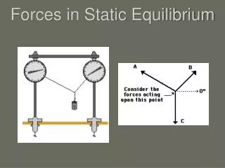
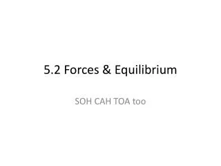
www.ekeeda.com Contact : 9029006464 Email : care@ekeeda.com P Coplanar Forces Coplanar Forces- -Equilibrium Equilibrium INTRODUCTION We have so far studied the three systems of forces and to find the resultant of the system. If the resultant of the force system happens to be zero, the system is said to be in a state of equilibrium. Various practical examples can illustrate the state of equilibrium of a system of forces like: 1)A lamp hanging from the ceiling is an example of Concurrent Force System in equilibrium. 2)Structures like buildings; dams etc. are examples of General Force System in equilibrium. 3)Students sitting on a bench in an example of parallel force system in equilibrium. In this chapter we shall study the conditions of equilibrium and applying these conditions with the help of free body diagrams, we shall learn to analyse a system in equilibrium. CONDITIONS OF EQUILIBRIUM (COE) A body is said to be in equilibrium if it is in a state of rest or uniform motion. This is precisely what Newton has stated in his first law of motion. For a body to be in equilibrium the resultant of the system should be zero. This implies that the sum of all forces should be zero i.e. ∑ F = 0 and the sum of all moments should also be zero i.e. ∑M = O The above two equations are the conditions of equilibrium in vector form. For a coplanar system of forces, the scalar equations of equilibrium are: ∑FX = O ---------- sum of all forces in x direction is zero ∑FY = 0 ---------- sum of all forces in y direction is zero ∑M = O ---------- sum of moments of all forces is zero 1
www.ekeeda.com Contact : 9029006464 Email : care@ekeeda.com FREE BODY DIAGRAM (FBD) A diagram formed by isolating the body from its surroundings and then showing all the forces acting on it is known as a Free Body Diagram". Such a diagram is required to be drawn for the body under analysis. For example consider a ladder AB of weight W resting against the smooth vertical wall and rough horizontal floor. If the ladder is under analysis then the FBD of the ladder shall show the weight W acting through its C.G., the normal reactions N and RB offered by the floor and the wall respectively and the friction force F at the rough floor. Consider a lamp of weight W, suspended from two strings AB and AC tied to the ceiling. The FBD of the lamp will show the weight W of the lamp and the tensions Tae and Tec in the strings AB and AC respectively. Importance of FBD 1.It is the first step in analysis of a body is equilibrium before applying the conditions of equilibrium. 2.It gives a clear picture of the body under analysis, and the effects of all the active and reactive forces and couples acting on it, can be accounted. By including the necessary dimensions in FBD, moments of the forces can be easily taken. 2
www.ekeeda.com Contact : 9029006464 Email : care@ekeeda.com TYPES OF SUPPORTS AND REACTIONS Whenever a body is supported, the support offers resistance, known as reaction. For example you are sitting on a chair while reading this book. Your weight is being supported by the chair which offers a force of resistance (reaction) upwards. Likewise let us see the different types of supports and the reactions they offer. Hinge Support A hinge allows free rotation of the body but does not allow the body to have any linear motion. It therefore offers a force reaction which can be split into horizontal and vertical components. Figure shows a body having a hinge support at A. The horizontal component HA and the vertical component VA of the support reaction are shown. When two bodies are connected such that the connection allows rotation between them and behaves as a hinge then such a connection is referred to as an internal hinge or pin connection. For example the two members of a scissor are connected by a pin which allows rotation but allows no linear movement. 3
www.ekeeda.com Contact : 9029006464 Email : care@ekeeda.com Roller Support A roller support is free to ro11 on a surface on which it rests. It offers a force reaction in a direction normal to the surface on which the roller is supported. A roller support may be shown in any of the three symbols as shown in fig (c). Fixed Support A fixed support neither allows any linear motion nor allows any rotation. It therefore offers a force reaction which can be split into a horizontal and a vertical component and also a moment reaction. Figure shows a beam having a fixed support at A. In addition to the horizontal component HA and the vertical component VA of the force reaction, there is a moment reaction MA. Such beams with one end fixed and other end free are called as cantilever beams. Smooth Surface Support A smooth surface offers a similar reaction as a roller support, i.e. a force reaction normal to the smooth surface. Fig. 3.6 shows a sphere supported between two smooth surfaces. Each surface offers one force reaction, normal to the surface at contact points. 4
www.ekeeda.com Contact : 9029006464 Email : care@ekeeda.com Rope/ String/Cable Support It offers a pull force in a direction away from the body. This force is commonly referred to as the tension force. Fig. shows a lamp suspended by two strings, each of them offers a tension force. Types of Loads The following types of loads can act on bodies. 1.Point load This load is concentrated at a point. Fig. shows point loads Fr , Fz, Fs acting on the beam. 2.Uniformly distributed load(u.d.l) In this loading the load of uniform intensity is spread over a length. u.d.l. can be converted into an equivalent point load by multiplying the load intensity with the length. This equivalent point load would act at center of the spread. Fig. Shows a u.d.l of intensity w N/m spread over a length AB of L miters. The equivalent point load of w x L would therefore act at L/2 from A. 3.Uniformly varying load.(u.v.l) In this loading, the load of uniformly varying intensity is spread over a length. u.v.l. can be converted into an equivalent load, which is equal to the area under the load diagram. The equivalent point load would act at the centroid of the load diagram. Refer Fig. 3.11 which shows a u.v.l. of intensit5r varying from zero to w N/m over a spread length of L metres. 5
www.ekeeda.com Contact : 9029006464 Email : care@ekeeda.com 4.Trapezoidal load In this loading pattern, the load intensity varies uniformly from a lower intensity of w1 N/m to a higher intensity of w2 N/m over a span of L metres. This loading is therefore a combination of a u.d.l. of intensity w1 and a u.v.l of intensity varying from zero to (w2 – w1) N/m. The u.d.I. portion is replaced by a point load of w1 x L, acting at L/2 from A. The u.v.l. portion is replaced by a point load of acting at L/3 from B. Thus a trapezoidal loading is replaced by two point loads as shown in fig. 5.Couple load We have studied about 'Couple' earlier in article 2.L2. A couple load acting on a body tends to cause rotation of the body. A couple load's location on the body is of no significance because couples are free vectors. Figure shows a three couples loads M1, M2 and M3 acting on the beam. Couple loads are represented by curved arrows. 6.Varying load In this loading, the loading intensity varies as some relation. Figure shows a varying distributed load of parabolic nature. The equivalent point load is the area under the curve acting at the C.G. of the area. 6
www.ekeeda.com Contact : 9029006464 Email : care@ekeeda.com EQUILIBRIUM OF A TWO FORCE BODY The concept of two forced body states “If only two forces act on a member and the member is in equilibrium then the two forces would be of equal magnitude, opposite in direction and collinear”. Members in equilibrium and subjected to two forces are referred to as two force members and their identification is useful in the solution of equilibrium problems. Fig. a (a) shows a frame consisting of three members AF, BC and DE. Member BC is isolated and shown in Fig. (b). Let RB and Rc be the pin reactions at B and C respectively. Since only two forces act on member BC, it is a two force member. Therefore RB : RC in magnitude, opposite in direction and are collinear (i.e. both are directed along line BC). EQUILIBRIUM OF A THREE FORCE BODY The concept of equilibrium of three force body states "If three coplanar forces act on a member and the member is in equilibrium, then the forces would be either Concurrent or Parallel”. Fig. (a) shows a uniform rod AB of weight W, one end of which is resting against a smooth vertical wall, while the other end is supported by a string. The member AEI is acted upon by three forces viz., a horizontal reaction Ra at A, the self-weight W acts through the C.G. of the rod, "while the tension T in the string acts at B. These three forces keep the rod in equilibrium and as per the concept of three force body, should therefore be concurrent. Refer Fig. (b). 7
www.ekeeda.com Contact : 9029006464 Email : care@ekeeda.com Fig. (a) shows a beam AB which is hinge supported at A and roller supported at B. Let a vertical load P be applied on the beam at C. we know that the reaction RB would be vertical. Since the beam is in equilibrium, hinge reaction Re would also be a vertical force. This is therefore a case of three parallel forces in equilibrium. Refer Fig. (b). LAMI'S THEOREM Lami's theorem deals with a particular case of equilibrium involving three forces only. It states "If three concurrent forces act on a body keeping it in equilibrium, then each force is proportional to sine of the angle between the other two forces". Fig. (a) shows a lamp held by two cables. The two tensile forces T1 and T2 in the string and the weight W of the lamp form a system of three forces in equilibrium. The forces would form a concurrent system. If is the angle between T2 and W, is the angle between T1 and W and is the angle between T1 and T2then according to Lami‟s theorem, T T W 1 2 sin sin sin Or in general for a system of three forces P, Q and R as shown in Fig. (c)we write Lami's equation as P Q R sin sin sin 8
www.ekeeda.com Contact : 9029006464 Email : care@ekeeda.com Note that while using Lami's theorem, the three concurrent forces should either act towards the point of concurrence or act away from it. If this is not the case then using the principle of transmissibility they can be made in the required form. Fig. (a) shows such a case for a sphere resting against smooth surfaces. The reactions Ra and Re act I to smooth surfaces. To apply Lami's equation the forces have been arranged acting concurrence as shown in Fig. (b). away from the point of concurrence as shown in fig (b) Proof: Let P, Q and R be the three concurrent forces in equilibrium as shown in fig (a) Since the forces are vectors they are added vectorially by head and tail connections. We get a closed triangular polygon as shown in Fig. (b). Applying sine rule we get, P Q R sin(180 ) sin(180 ) sin(180 ) P Q R sin …………proved sin sin 9
www.ekeeda.com Contact : 9029006464 Email : care@ekeeda.com EQUILIBRANT FORCE An unbalanced force system can be brought to equilibrium by adding an equilibrant force in the system. The equilibrant force has magnitude, direction and point of application as of the resultant of the system but has a sense opposite to that of Resultant. To find the Equilibrant of a force system we first find magnitude, direction and. Location of the resultant of the force system shall therefore of the same magnitude, direction and location as of the resultant having an opposite sense to that of the Resultant. EXERCISE 1 1.Draw neat FBDs for the following supported bodies in equilibrium. Take all plane surfaces as smooth. 10
www.ekeeda.com Contact : 9029006464 Email : care@ekeeda.com 2.A beam AB is loaded as shown. Find support reactions. 3.For the beam shown in the figure find the reactions. 4.Find analytically the support reaction at B d load P for the beam shown in figure if reaction at support A is Zero. 5.Figure shows beam hinged at A and roller supported at B. The L shaped portion DEF is an extended part beam AB. For the loading shown, find support reactions. 6.Find support reactions. Portion CD is an extended part of the beam AB 7.Determine the actions developed in cantilever beam as shown in figure. 8.Find the reactions the supports of the am loaded as shown in figure. 11
www.ekeeda.com Contact : 9029006464 Email : care@ekeeda.com 9.A simply supported am AB of span 3m, overhanging on both side is loaded as down in figure. Find the support reactions. 10.Find the reactions at the supports of the beam AB loaded as shown. 11.Find the support reactions for the beam loaded and supported as shown in I figure. 12.Determine support reactions for the beam shown. 13.The figure shows a 10 kg lamp supported by two cables AB and AC. Find the tension in each cable 14.A sphere of 500 N weight is lodged between two smooth surfaces as shown. Find reactions at contact points A and B. 12
www.ekeeda.com Contact : 9029006464 Email : care@ekeeda.com 15.A roller of weight W = 1000 N rest on a smooth incline plane. It is kept from rolling down the plane by a string AC. Find the tension in the string and reaction at the point of contact D. 16.A small boat is held in static by means of three taut ropes OA, OB and OC as shown. The water in the river exerts a force on the boat in the direction of flow a)If the tension in OA and OB are 1 kN an 0.6 kN respectively determine the force F, exerted by the flow on the boat and the tension in rope OC. b)If rope OC breaks, will the boat remain equilibrium? What is the new tension ropes OA and OB after OC breaks? 17.A straight vertical mast 4 m long is pinned to the ground and stayed by mean a cable at a distance of 3 m from the bottom as shown. If a horizontal force of 5 kN acts at the top, determine the tension in the cable and reaction at the hinge. 18.Figure shows a crank lever ABC with a tension spring (T). The lever weighs 0.2N/mm determine the tension developed in the spring, when a load of 1OON is applied at A. 13
www.ekeeda.com Contact : 9029006464 Email : care@ekeeda.com 19.Determine the tension T the cable and the reaction at r support A for the beam loaded as shown. Neglect weight the beam and the size of the pulley. 20.A uniform wheel of 800 mm diameter weighing 6 kN rests against a rigid rectangular block of 150 mm height as shown in figure. Find the least pull, through the center of the wheel, required just to turn the wheel over the edge A of the block. Also find the 4 reaction on the block. Take all the surface to be smooth. 21.A uniform circular wire of radius 50 cm and weight of 0.1 N/cm of length is suspended from a hinge at A. For the given equilibrium position i.e. diameter AB being vertical, determine the horizontal force P required to keep the bar in this position. Hint: The weight of the wire acts through its centre of gravity G. Refer table in Chapter 6 for location of G. 22.A non-uniform heavy rod AB of length 3 m libs on horizontal ground. To lift the end B off the ground needs a vertical force of 200 N. To lift A end off the ground needs a force of 160 N. Find the weight of the rod and the position of centre of mass. 23.A weightless bar is placed in a horizontal position on the smooth inclines as shown. Find x at which the 200 N force should be placed from point B to keep the bar horizontal. 14
www.ekeeda.com Contact : 9029006464 Email : care@ekeeda.com 24.The force system shown has neither a resultant force nor a resultant couple. Find magnitude of forces P, Q and R. Hint: The system is in equilibrium. 25.Forces act on the plate ABCD as shown in figure. The distance AB is 4 m. Given that the plate is in equilibrium find. (i) force F (ii) angle , and (iii) the distance AD 26.Determine the equilibrant of the force system shown in figure. 27.A man raises a 12 kg joist of length 4m by pulling the rope. Find the tension in the rope and the reaction at A. 28.A concrete dam has rectangular cross section of height h and width b and is subjected to a water pressure on one side. Determine the minimum width 'b' of the dam if the dam is not to overturn about the point B when h = 4m. Assume density of water = 1OOO kg/m3 an density of concrete : 24OO kg/m, 15
www.ekeeda.com Contact : 9029006464 Email : care@ekeeda.com EQUILIBRIUM OF CONNECTED BODIES When two or more rigid bodies are connected to each other, they form a system of connected bodies. Though the COE can be applied to the entire system, the individual bodies can also be isolated from the internal connections and conditions of equilibrium can be applied to them too. In a system of connected bodies if there are more than three unknowns in the system we isolate the connected system from the internal connection and apply COE to isolated bodies as well as COE to the system, thus getting sufficient equations for the many unknowns in the system. The internal connection could be a hinge (commonly referred to as pin), roller, smooth surface or a rope. At the internal connection say of a hinge, the sense of components of reaction are assumed on any one of the bodies initially and the opposite sense is assumed on the other body (since an internal force, when exposed, occurs in pair, having the same magnitude, collinear and opposite in sence) Fig. (a) shows a system of connected bodies. There are two bodies AC and BC in the system. The external supports are the hinge at A and roller at B. The internal connection is a hinge at C. Fig. (b) show the FBD of the whole system. The two bodies can be isolated from the internal hinge C. Fig. 3.20 (c) shows the FBD's of the isolated bodies. Note that the sense of Hc and Vc on the member AC is opposite to that on member BC. 16
www.ekeeda.com Contact : 9029006464 Email : care@ekeeda.com The following examples will help us understand the concept behind a system of connected bodies, the way we isolate the bodies, show the internal forces in pair, in opposite sense at the internal connection and finally apply COE to the system as well as to the isolated bodies, to get the unknowns. EXERCISE 2 1.A two span beam ABCD is loaded as shown. Calculate support reaction. 2.A beam ABC, fixed at A and roller supported at C is internally connected by a pin at B. Determine the support reactions. 3.Find the reactions of the beam shown in figure. 4.The beam is loaded as shown in figure. Determine the reactions at fixed support roller support B and reaction at internal hinge C. 5.Find the maximum weight W that can be lifted by the crane without tipping over the wheel B'as shown in figure. Calculate the corresponding reaction at 'P' and 'Q'. Weight of crane is 1OO KN acting through „C‟ 17
www.ekeeda.com Contact : 9029006464 Email : care@ekeeda.com 6.A two bar mechanism is internally pinned at B. It is loaded .1 supported as shown. Calculate force P required at C to maintain configuration. 7.A beam is supported and loaded as shown. Find reactions at the supports using equations of equilibrium. C is an internal hinge. 8.Two smooth spheres of weight 100 N and of radius 250 mm each are in equilibrium in horizontal channel of width 900 mm as shown. Find the reactions at the surface of contact A, I and D assuming all smooth surfaces. 9.A 60ON cylinder is supported by the frame- I as shown in figure 4. The frame is hinged D. Determine the reactions developed at .act points A, B, C and D. Neglect the weight of frame and assume all contact surfaces are smooth 18
www.ekeeda.com Contact : 9029006464 Email : care@ekeeda.com 10.Sphere A = 1000 N rests on two spheres Band C of weight 900 N each. The spheres B and C are connected by an inextensible string of length L = 6OO mm. Assuming smooth contacts and radius of spheres to be 20O mm, determine the reactions at all contact points 1 to 4 and also the force in the string. 11.Two spheres A and B of weight 1OOO N and 750 N respectively are kept as shown in figure. Determine the reactions at all contact points 1 2, 3 and 4. Radius of A = 4OO mm and radius of B = 300 mm. 12.Determine the reactions at points of contact 1, 2 and 3. Assume smooth surfaces. Take ma=1kg,m"=4kg. 13.Find the reactions at A, B, C and D. Neglect friction. (notion stands for diameter) 19
www.ekeeda.com Contact : 9029006464 Email : care@ekeeda.com 14.A cylinder of diameter 1 m weighing 1000 N and another block weighing 500 N supported by a beam of length 7 m and weighing 25.r the help of a cord as shown the surfaces of contact are frictionless, determine tension in cord and reaction at point of contacts. 15.Two homogenous solid cylinders of identical weight of l0 N and radius of 0.4 m are resting against inclined wall and, ring ground as shown. Assuming smooth surfaces find reactions at A, B and C of the contact points. 16.Two identical rollers each of weight 500 N and radius r are kept on a right angle frame ABC having negligible weight. Assuming smooth surfaces, find the reactions induced at all contact surfaces. 17.A 30 kg pipe is supported at „A‟ by a system of five chords determine the force in each chord for equilibrium. 20
www.ekeeda.com Contact : 9029006464 Email : care@ekeeda.com ANALYSIS OF PIN JOINTED FRAMES Frames are structures which support loads. Frames are a system of connected bodies where the members are interconnected by hinges (pins). Loads can be applied anywhere on the member of the frame. Since frames are connected by pins, we are required to find out the forces acting on the connecting pins on a loaded frame. These forces are found out by applying COE to the entire frame and also to the individual members after isolating the members. On isolating at the connecting hinge (pin) the forces occur in pair, equal in magnitude, collinear and opposite in sense. The following examples explain the method of analysis of frames. EXERCISE 3 1)Calculate support reactions at A and D in the frame. All pin connections are frictionless. 2)An X frame is loaded and Find the horizontal and components of reaction at A and C. 3)Determine the reactions at A, B and C for the pin-jointed frame loaded as shown. 21
www.ekeeda.com Contact : 9029006464 Email : care@ekeeda.com 4)Determine the reactions at supports A, B and C for the frame loaded as shown. 5)Find the reactions at and E if the frame shown loaded at A by a load of is the force on pin at C. lkN supports D in figure is 1 kN. What is the force on pin at C. 6)For the frame and loading shown determine the components of all forces acting on member ABD. 7)Find the reactions at the supports A and E of the frame shown in figure. Also the force in pin at B. 22
www.ekeeda.com Contact : 9029006464 Email : care@ekeeda.com 8)Figure shows a frame in which the pulley at D has a mass of 2OO kg. Neglecting the weights of the bars find out the components of hinge reactions at A, B and c. 9)Frame shown supports horizontal forces. Determine the forces acting on pins A,B,C and D 10)Determine support reactions and C for the pin connected frame. 11)Determine reactions at A, B and C 'the frame shown in figure. 23
www.ekeeda.com Contact : 9029006464 Email : care@ekeeda.com 12)For a system of connected bodies find the support reactions. EXERCISE 4 THEORY QUESTIONS Q.1.What are the necessary conditions for a body to be in a state of equilibrium. Q.2.Define the term Free Body Diagram. What is the significance of drawing a free body diagram. Q.3.List and explain different types of supports and their reactions. Q.4.What is equilibrium of two force body. Q.5.What is equilibrium of three force body. Q.6.State and prove Lami's theorem of three forces Q.7.Define equilibrant. 24
www.ekeeda.com Contact : 9029006464 Email : care@ekeeda.com UNIVERSITY QUESTIONS 1.Find the reactions at „A‟. (10 Marks) 2.Three cylinders are piled up in a rectangular channel as shown in figure. Determine 10 the reactions between cylinders A, B and C with channel surfaces. Assume all smooth surfaces. (10 Marks) w w w 150 , 400 200 N N N r r r 4 6 5 cm cm cm A A B B c c 3.Two spheres rests on a smooth surfaces as shown in figure. Find the reactions at points of contact 1,2,3 and 4. (10 Marks) w r 500 , 0.20 N w m 200 , N r 0.25 m A B A B 4.State and prove Lami‟s Theorem. (4 Marks) 25
www.ekeeda.com Contact : 9029006464 Email : care@ekeeda.com 5.A member ABC is loaded by distributed load and pure moment as shown in the fig. Find the i) magnitude and ii) position along AC of the resultant. (6 Marks) 6.A cylinder weighing 1000 N and 1.5 m diameter is supported by a beam AB of length 6 m and weight 400 N as shown in fig. Neglecting friction at the surface of contacts, determine i) Wall reaction at D. ii) Tension in the cable BC and iii) Hinged reaction at support A. (8 Marks) 7.Find the support reactions at A and B for the beam shown in fig. (8 Marks) B W 8.A cylinder dia. 40 cm, hangs by a cable AB = 40 cm rests , 1000 B N , against a smooth wall. Find out reaction at C and TAB. (4 Marks) 26
www.ekeeda.com Contact : 9029006464 Email : care@ekeeda.com 9.Find out resultant of given (lever) force system w.r.t. „„B‟‟. (4 Marks) 10.Two identical cylinders dia 100 mm weight 200 N are placed as shown. All contacts are smooth. Find out reactions at A, B and C. (8 Marks) 11. Find the support reactions at Hinge A and Roller B. (8 Marks) 12.A cylinder of weight 500 N is kept on two inclined places as shown in the fig. Determine the reactions at the contact points A and B (4 Marks) 13.A Cylinder of weight 300 N is help in equilibrium as shown in fig. given below. Determine the tension in the string AD and reaction at C and B. The length of AE = 750 mm. (8 Marks) 27
www.ekeeda.com Contact : 9029006464 Email : care@ekeeda.com 14.Find the reactions at supports B and F for the beam loaded as shown in the fig. below. (8 Marks) 15.Two cylilnders are kept in a channel as shown in figure. Determine the reactions at all the contact points A,B,C and D. Assume all surfaces smooth. (8 Marks) 16.Find the support reaction at B and the load P, for the beam shown in figure if the reaction at support A is zero. (8 Marks) 17.Determine the tensions in cords AB & BC for equilibrium of 30kg block (8 Marks) 28
www.ekeeda.com Contact : 9029006464 Email : care@ekeeda.com 18.Replace the force system by a single force w.r.to point C. (6 Marks) 19.A bar of 3m. length & negligible weight rests in horizontal position on two smooth inclined planes Determine the distance x at which the load Q = 150 N should be placed from point 8 to keep the bar horizontal. (8 Marks) 20.Find the support reaction for the beam. (8 Marks) 29