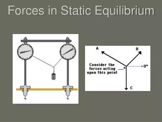
Forces and equilibrium
Forces and equilibrium. Forces and Equilibrium. Scalars and vectors. Types of forces. Resultant of forces. Equilibrium of particles. Scalar and Vectors. Scalar - a physical quantity that is completely described by a real number e.g. time, length, mass, temperature.


Forces and equilibrium
E N D
Presentation Transcript
Forces and Equilibrium Scalars and vectors Types of forces Resultant of forces Equilibrium of particles
Scalar and Vectors • Scalar - a physical quantity that is completely described by a real number • e.g. time, length, mass, temperature • Vector - is described by both magnitude (nonnegative real number) and direction • e.g. position of a point in space relative to another point, forces • - represented by bold-faced letters: u, a, W • - magnitude of vector u = |u| • - graphical representation of vectors: arrows • - direction of arrow shows the direction of vector • - length of arrow magnitude of vector
Vectors Example: rAB - position of point B relative to point A - direction from point A to point B - distance between A and B = |rAB|
External force Internal force Types of forces Types of forces
Resultant of force in 2Dimension • Scalar • Added 4 m2 and 3 m2 = 7 m2 • Vector • Added 4 km and 3 km = sum and direction • Resultant = single vector giving the result of the addition of the original two or more vectors.
Q Q P P R = P + Q Q R P Q Q P Resultant of forces: Graphical • Triangle rule - sum of vector from tail of P to head of Q • Parallelogram rule - the sum is independent of the order in which the vectors are placed head to tail - vector addition is commutative P + Q = Q + P = R - vector subtraction R = P Q • R - resultant of two forces, P and Q
Q P R = P + Q Law of sine, Resultant of forces: Analytical • Trigonometric: C B Law of cosine, A Pythagorean theorem • Resolution of vectors: ‘Resolve’ vectors into components using the x and y axes system. We use the “unit vectors” i and j to designate the x and y axes
Example 1: Figure shows an initial design sketch of part of the roof of a sports stadium to be supported by the cables AB and AC. The forces the cables exert on the pylon to which they are attached are represented by the vectors FAB and FAC. The magnitude of the forces are |FAB| = 100 kN and |FAC| = 60 kN. Determine the magnitude and direction of the sum of the forces exerted on the pylon by the cables (a) graphically and (b) using trigonometry.
Solution: • Graphically construct the parallelogram rule with FAB and FAC proportional to their magnitudes: • By measuring the figure, we estimate the magnitude of the vector FAB + FACto be 160 kN and its direction to be 19° above the horizontal.
Solution: (b) Consider the parallelogram rule: Since = 180° 30 ° = 150° Applying law of cosine to the triangle: Magnitude |FAB + FAC| = 154.9 kN
To determine the angle between FAB + FACand the horizontal, apply law of sines to shaded triangle:
Example 2: Determine the horizontal and vertical components of P Solution:
Example The ring shown in figure is subjected to two forces, Fl and F2. If it is required that the resultant force have a magnitude of 1 kN and be directed vertically downward, determine the magnitudes of Fl and F2, provided = 30°.
Solution: Vector addition sketch according to the parallelogram law:
Using the law of sines: F1 = 635 N F2 = 446 N
Trigonometric solution - law of cosines, Example 4: Determine the resultant of forces that acts on bolt A. Solution:
There are four concurrent cable forces acting on the bracket. How do you determine the resultant force acting on the bracket ?
Resultant of forces (component method) • A single force can be broken up into two separated forces • To add vectors analytically using the method components , one should be proceed according to the step. Fy F Fx
Resolve each vector into a horizontal and vertical component • Add the vertical components, Ry=∑Fy. • Add the horizontal components, Rx = ∑Fx • Combine the horizontal and vertical components to obtain a single resultant vector.
Exercise 1 Three concurrent forces are acting on a bracket. Find the magnitude and angle of the resultant force by resolving the forces.
Solution: F1 = { 15 sin 40° i + 15 cos 40°j } kN = { 9.642 i + 11.49 j} kN F2 = { -(12/13)26 i + (5/13)26 j } kN = { -24 i + 10 j } kN F3 = { 36 cos 30° i– 36 sin 30°j } kN = { 31.18 i– 18 j } kN I = x axis, j = y axis
y FR x Summing up all the i and j components respectively, we get, FR = { (9.642 – 24 + 31.18) i + (11.49 + 10 – 18) j } kN = { 16.82 i + 3.49 j } kN FR = ((16.82)2 + (3.49)2)1/2 = 17.2 kN = tan-1(3.49/16.82) = 11.7°
+y -Z +X -X +Z -y Resultant force in 3 Dimension
y 6N R x 4N 3N R1 z R=7.81 N, coordinates (4,6,3)
Vector equation • Or known as Cartesian vector • Used right hand coordinate system
Example 2.13 • Express the force F shown in Figure 2.23 as a Cartesian vector
Since only two coordinate direction angles are specified, the third angle α must be determined using equation • Hence, two possibilities exist, namely, α = cos-1(0.5) = 60o or α = cos-1(0.5) = 120o
By inspection, it is necessary that α = 60o, since Fxmust be in the +x direction, with F = 200 N, we have F = F cosαi + F cosβj+ F cosγk F = (200 cos 60oN)i + ( 200 cos 60o N)j + ( 200 cos 45o)k F = {100.0i + 100.0j + 141.4k} N • Show that indeed the magnitude of F = 200N
Equilibrium of a particle • The term “particle” used in statics to describe a body when; • the size and shape of the body will not significantly affect the solution of the problem being considered. • the mass of the body can be assumed to be concentrated at a point. • A particle can be subjected only to a system of concurrent forces and that the necessary and sufficient conditions for equilibrium can be expressed mathematically as R = F = 0 where F is the vector sum of all forces acting on the particle. • To apply the equation of equilibrium --- account for allthe known and unknown forces (F) which act on the particle.
APPLICATIONS For a spool of given weight, what are the forces in cables AB and AC ?
APPLICATIONS (continued) For a given cable strength, what is the maximum weight that can be lifted ?
Procedure for Drawing a Free-Body Diagram • Draw Outlined Shape:Imagine the particle to be isolated or cut "free" from its surroundings by drawing its outlined shape. • Show all Forces: Indicate on this sketch all the forces that act on the particle. These forces can be active forces, which tend to set the particle in motion, or they can be reactive forces which are the result of the constraints or supports that tend to prevent motion. To account for all these forces, it may help to trace around the particle's boundary, carefully noting each force acting on it. • Identify Each Force:The forces that are known should be labeled with their proper magnitudes and directions. Letters are used to represent the magnitudes and directions of forces that are unknown.
EQUILIBRIUM OF PARTICLE IN 2-D This is an example of a 2-D or coplanar force system. If the whole assembly is in equilibrium, then particle A is also in equilibrium. To determine the tensions in the cables for a given weight of the engine, we need to learn how to draw a free body diagram and apply equations of equilibrium.
THE WHAT, WHY AND HOW OF A FREE BODY DIAGRAM (FBD) Free Body Diagrams are one of the most important things for you to know how to draw and use. What ? - It is a drawing that shows all external forces acting on the particle. Why ? - It helps you write the equations of equilibrium used to solve for the unknowns (usually forces or angles).
How ? 1. Imagine the particle to be isolated or cut free from its surroundings. 2. Show all the forces that act on the particle. Active forces: They want to move the particle. Reactive forces: They tend to resist the motion. 3. Identify each force and show all known magnitudes and directions. Show all unknown magnitudes and / or directions as variables . A Note : Engine mass = 250 Kg FBD at A
EQUATIONS OF 2-D EQUILIBRIUM Since particle A is in equilibrium, the net force at A is zero. So FAB + FAD+FAC= 0 or F = 0 A FBD at A In general, for a particle in equilibrium, F = 0or Fxi+ Fyj = 0 = 0 i+0 j(A vector equation) • Or, written in a scalar form, • Fx= 0and Fy= 0 • These are two scalar equations of equilibrium (EofE). They can be used to solve for up to two unknowns.
EXAMPLE Note : Engine mass = 250 Kg FBD at A Write the scalar EofE: + Fx = TBcos 30º – TD = 0 + Fy = TB sin 30º – 2.452 kN = 0 Solving the second equation gives: TB = 4.90 kN From the first equation, we get: TD = 4.25 kN
Two-Dimensional Problems R = Rx + Ry = Rn + Rt = 0 = Rxi + Ryj = Rnen+ Rtet = 0 = Fxi + Fyj = Fnen+ Ftet = 0 Satisfy only if Rx = Rxi= Fxi= 0 Ry= Ryj= Fyj= 0 Rn = Rnen= Fnen = 0 Rt= Rtet = Ftet = 0
Example 2.14 A free-body diagram of a particle subjected to the action of four forces is shown in Fig.2.29. Determine the magnitudes of forces Fl and F2 so that the particle is in equilibrium
Solution +Fx= F1x + F2x + F3x + F4x = 0 = F1cos 60 + F2cos 30 - 40 cos 56 - 10 cos15 = 0 = 0.5 F1 + 0.866 F2 – 22.37 – 9.659 = 0 From which F1 + 1.732 F2 = 64.06 (a) +Fy= F1y + F2y + F3y + F4y = 0 = F1 sin 60 + F2 sin 30 - 40 sin 56 + 10 sin 15 = 0 = 0.8660 F1 + 0.5 F2 – 33.16 + 2.588 = 0 From which F1 + 0.5774 F2 = 35.30 (b) Solving Eqs (a) and (b) simultaneously yields F1 = 20.9 kip F2 = 24.9 kip
GROUP PROBLEM SOLVING Given: The car is towed at constant speed by the 600 N force and the angle is 25°. Find: The forces in the ropes AB and AC. Plan: 1. Draw a FBD for point A. 2. Apply the EofE to solve for the forces in ropes AB and AC.
600 N FBD at point A A 30° 25° FAC FAB GROUP PROBLEM SOLVING (continued) Applying the scalar EofE at A, we get; + Fx = FACcos 30° – FABcos 25° = 0 + Fy = -FAC sin 30° – FAB sin 25° + 600 = 0 Solving the above equations, we get; FAB = 634 N FAC = 664 N
EQUILIBRIUM OF PARTICLE IN 3-D Three-Dimensional Problems R = F = 0 = Rx + Ry + Rz = 0 = Rxi + Ryj + Rzk = 0 = Fxi + Fyj + Fzk = 0 satisfied only if Rx = Rxi= Fxi= 0 Ry= Ryj= Fyj= 0 Rz = Rzk= Fzk = 0
Example 2.17 • A 90-lb load is suspended from the hook shown in Figure 2.28(a). The load is supported by two cables and a spring having a stiffness k = 500 lb/ft. Determine the force in the cables and the stretch of the spring for equilibrium. Cable AD lies in the x-y plane and cable AC lies in the x-z plane.
Equation of equilibrium Fx= 0 FD sin 30 - (4/5)FC = 0 (a) Fy= 0 -FDcos 30 + FB = 0 (b) Fz= 0 (3/5) FC – 90 lb = 0 (c) • Solving Eq. (c) for FC, then Eq (a) for FD, and finally Eq. (b) for FB, yields, • FC = 150 lb Ans • FD = 240 lb Ans • FB = 208 lb Ans
The strech of spring is therefore FB = ksAB 208 lb = 500 lb/ft (sAB) sAB= 0.416 ft Ans