Download
1 / 6
60 likes | 457 Views
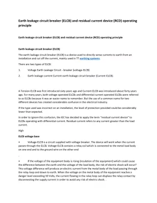
A Tension-ELCB was first introduced sixty years ago and Current-ELCB was introduced about forty years ago. For many years, both voltage operated ELCBs and differential current operated ELCBs were referred to as ELCBs because it was an easier name to remember.

E N D
Earth leakage circuit breaker (ELCB) and residual current device (RCD) operating principle Earth leakage circuit breaker (ELCB) and residual current device (RCD) operating principle Earth leakage circuit breaker (ELCB) The earth leakage circuit breaker (ELCB) is a device used to directly sense currents to earth from an installation and cut off the current, mainly used in TT earthing systems. There are two types of ELCB: 1. Voltage Earth Leakage Circuit - breaker (voltage-ELCB) 2. Earth leakage current Current earth leakage circuit breaker (Current-ELCB). A Tension-ELCB was first introduced sixty years ago and Current-ELCB was introduced about forty years ago. For many years, both voltage operated ELCBs and differential current operated ELCBs were referred to as ELCBs because it was an easier name to remember. But the use of a common name for two different devices has created considerable confusion in the electrical industry. If the type used was incorrect on an installation, the level of protection provided could be considerably lower than expected. In order to ignore this confusion, the IEC has decided to apply the term “residual current device” to ELCBs operating with differential current. Residual current refers to any current greater than the load current. High ELCB voltage base • passes through the ELCB. Voltage-ELCB contains a relay coil which is connected to the metal load body on one end and to the ground wire on the other end Voltage-ELCB is a circuit supplied with voltage breaker. The device will work when the current . • the difference between the earth and the voltage of the load body, the risk of electric shock will occur? This voltage difference will produce an electric current from the metal body of the load passing through the relay loop and down to earth. When the voltage on the metal body of the equipment reaches a danger level exceeding 50 Volts, the current flowing in the relay loop can displace the relay contact by disconnecting the supply current in order to avoid any risk of electric shock. . If the voltage of the equipment body is rising (insulation of the equipment) which could cause
. • sufficient voltage appears on the ELCB sense coil, the ELCB will de-energize and remain so until a manual reset. A voltage sensing ELCB does not detect fault currents from living things to other earthed bodies. The ELCB detects the fault currents of the earth wire (earth) in the installation it protects. If • voltage on the ground wire was greater than 50 volts. These ELCBs monitored the voltage on the ground wire and disconnected the power if the . • voltage and a circuit earth, they will disconnect the power supply. However, if the fault is between a live earth and another earth (a person or a metal water pipe, for example), they will NOT disconnect because the voltage on the circuit earth will not change. Even if the fault is between a live earth and a circuit earth, parallel earth paths created through gas or water lines can cause the ELCB to bypass. Most of the fault current will flow through the gas or water lines, since These devices are no longer used due to its disadvantages, such as if the fault is between live • the device. They depend on the voltage returning to the trip via the earth wire in the event of a fault and offer only limited protection to the installation and no personal protection. You must use a 30mA GFCI for all appliances and extension cords that can be used outdoors at a minimum. To identify an ELCB, you need to look for green or green and yellow ground wires that go into Benefits • cause fewer nuisance tripping. ELCBs have an advantage over RCDs: they are less sensitive to fault conditions and therefore . • this is not always the case. So there are situations in which an ELCB can trigger in an awkward way. Although the voltage and current on the ground line is usually the fault current of a live wire, . • cause a voltage gradient in the ground, which will present the ELCB detection coil with sufficient voltage to trigger it. When an installation has two ground connections, a nearby high current lightning strike will . • earth leakage current in the other building can increase the local earth potential and cause a voltage difference between two earths, which again triggers the triggering of the ELCB. If the installation earth rod is placed close to the earth socket of a neighboring building, a high . • reduced due to old equipment, by heating elements or by rain, the insulation resistance may be reduced If there is a build-up or charge of currents caused by elements whose insulation resistance is
due to humidity monitoring. If there is a mA value equal to the ELCB nominal value, this can cause an unwanted tripping. . • installation will no longer be properly earthed. If one of the earth wires is disconnected from the ELCB, it will no longer trip or often, the . • and RCDs, but ELCBs are on average much older than RCBs, so an older ELCB is more likely to have a rare fault current waveform that it does not respond to. not. Some ELCBs do not respond to the current corrected fault. This problem is common to ELCBs . • additional connection to ground on the protected system could disable the detector. The voltage powered ELCBs are required for a second connection and the possibility that any . • The nuisances are triggered especially during thunderstorms. Disadvantages • They do not detect faults that do not pass current through the CPC to the earth stake. • protection, since grounding systems usually use a common ground. They do not make it easy to split a building system into several sections with independent fault • such as metal pipes, a TN-S earth, or a combined TN-CS neutral to earth. They can be triggered by external voltages from something connected to the earthing system, • the electronic ballast to trip. Leaking electrical devices, such as some water heaters, washing machines and stoves, can cause • ELCBs introduce additional resistance and an additional point of failure in the grounding system. Can we assume that our electrical system is protected from earth protection or not just by pressing the ELCB test switch? • of ELCB. The test pushbutton will test whether the ELCB unit is functioning properly or not. Can we assume that if ELCB triggers the trip after pressing the TEST switch of ELCB, your system is protected against earth? So you are wrong. Checking the health of ELCB is simple and you can do it easily by pressing the TEST push button . • but this test does not confirm that the ELCB will trip if there is a risk of electric shock. It is a truly sad fact that this misunderstanding has left many homes completely safe from the risk of electric shocks. The test facility provided on the home ELCB will only confirm the health status of the ELCB unit, .
• The second requirement for the proper functioning of a home shock protection system is electrical grounding. This causes us or worries us to think about the second basic requirement of earth protection. . • without a functional grounding (proper grounding of the electrical system), your house is absolutely not protected against electric shock, even if you have installed ELCB and its TEST switch shows a correct result. Just looking after the ELCB is not enough. The electrical grounding system must also be in good working order for the shock protection system to function. In addition to the routine inspections which should be performed by a qualified electrician, this grounding should preferably be inspected regularly by the homeowner, at shorter intervals and should be poured. Presumably ELCB is the brain for shock protection and grounding as a backbone. Therefore, Current-operated ELCB (RCB) • protect against earth leakage. The two circuit conductors (supply and return) pass through a detection coil; any current imbalance means that the magnetic field does not cancel out perfectly. The device detects the imbalance and triggers the contact. ELCBs currently in use are generally referred to as Residual Current Devices (RCDs). These also . • operation today are called residual current devices. However, some companies use the term ELCB to distinguish high-sensitivity three-phase current devices that trip in the milli-amp range from traditional three-phase ground fault devices that operate at much higher currents. When the term ELCB is used, it usually means voltage device. Similar devices that are in • Typical RCB circuit : • The power coil, neutral coil, and search coil are all wound on a common transformer core. . • the neutral coil. The phase and neutral windings are wound so as to produce an opposite magnetic flux. With the same current flowing through both coils, their magnetic effect is canceled out if the circuit is in good condition. On a healthy circuit, the same current flows through the phase coil, the load, and back through
. • output connection of the RCB circuit, the current returned by the neutral coil has been reduced. Then the magnetic flux inside the transformer core is no longer balanced. The total sum of the opposite magnetic flux is no longer zero. This net remaining flow is what we call a residual flow. In the event of a fault or earth leakage in the load circuit or between the load circuit and the . • search coil winding. This action produces an electromotive force (for example) on the search coil. An electromotive force is actually an alternating voltage. The voltage induced across the search coil generates a current within the trip circuit wiring. It is this current which actuates the trip coil of the circuit breaker. Since the trip current is controlled by the residual magnetic flux (the resulting flux, the net effect between the two fluxes) between the phase coil and the neutral coil, it is called the residual current. The periodically changing residual flux inside the transformer core crosses the path with the . • Residual Current Circuit Breaker (RCCB) or Residual Current Diagram (RCD). The incoming current must first pass through the circuit breaker before passing to the phase coil. The neutral return circuit passes through the second pole of the circuit breaker. During tripping, when a fault is detected, the phase and neutral connections are isolated. With a circuit breaker incorporated as part of the circuit, the assembled system is called a . </ p> • denoted IΔn. The preferred values have been defined by the IEC, thus making it possible to divide the RCDs into three groups according to their IΔn value. The sensitivity of the differential is expressed as the nominal residual operating current, • High sensitivity ( HS ): 6-10-30mA (for protection against direct contact / injury) • types of differential RCDs according to the characteristics of the fault current. Standard IEC 60755 (General requirements for residual current protection devices) defines three • AC type : RCD tripping for residual sinusoidal alternating currents RCB sensitivity: • Medium sensitivity ( MME ): 100-300-500-1000 mA (for fire protection) • Low sensitivity ( LS ): 3- 10-30 A (generally for machine protection) Types of RCB: Type UNE: RCD for which tripping is assured • for residual sinusoidal alternating currents • for residual pulsed direct currents
• with or without phase angle control, regardless of polarity. For residual pulsed direct currents superimposed on a homogeneous direct current of 0.006 A, Type B: RCD for which tripping is assured • as for type A • for sinusoidal residual currents up to 1000 Hz • for residual sinusoidal currents superimposed by a pure direct current • for pulsed direct currents superimposed by a pure direct current • for residual currents that may result from rectifying circuits o three-pulse star connection or six-pulse bridge connection o of polarity line-to-line two-pulse bridge connection with or without phase angle monitoring, independent o There are two groups of devices: RCB pause time: 1 g (general use) for instantaneous DDR (that is to say, without limit) • Minimum break time: immediate • Maximum pause time: 200 ms for 1x IΔn, 150 ms for 2x IΔn and 40 ms for 5x IΔn 2. S (selective) or T (delayed) for DDR with a short time delay (typically used in circuits containing overvoltage limiters) • Minimum pause time: 130 ms for 1x IΔn, 60 ms for 2x IΔn and 50 ms for 5x IΔn • Maximum pause time: 500 ms for 1x IΔn, 200 ms for 2x IΔn and 150 ms for 5x IΔn Burraq Engineering Solutions is providing practically electrical courses in Lahore. We offer PLC course, SOLAR SYSTEM Installation and DESIGN COURSE, ETAP course, DIALAX course, Panel FABRICATION course, VFD course, ADVANCED Course Panel, SWITCHERGEAR design course, Building Electrical design course and all electrical diploma courses in Lahore.