Inertial Navigation
Inertial Navigation. Advantages instantaneous output of position and velocity completely self contained all weather global operation very accurate azimuth and vertical vector measurement error characteristics are known and can be modeled quite well works well in hybrid systems.

Inertial Navigation
E N D
Presentation Transcript
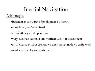
Inertial Navigation • Advantages • instantaneous output of position and velocity • completely self contained • all weather global operation • very accurate azimuth and vertical vector measurement • error characteristics are known and can be modeled quite well • works well in hybrid systems
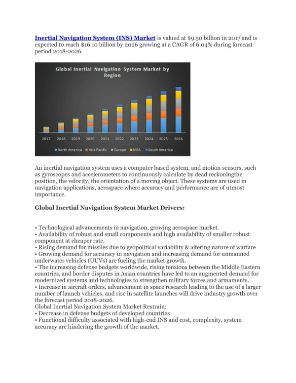
Inertial Navigation • Disadvantages • Position/velocity information degrade with time (1-2NM/hour). • Equipment is expensive ($250,000/system) - older systems had relatively high failure rates and were expensive to maintain • newer systems are much more reliable but still expensive to repair • Initial alignment is necessary - not much of a disadvantage for commercial airline operations (12-20 minutes)
Inertial Navigation – Basic Principle • If we can measure the acceleration of a vehicle we can • integrate the acceleration to get velocity • integrate the velocity to get position • Then, assuming that we know the initial position and velocity we can determine the position of the vehicle at ant time t.
Inertial Navigation – The Fly in the Ointment • The main problem is that the accelerometer can not tell the difference between vehicle acceleration and gravity • We therefore have to find a way of separating the effect of gravity and the effect of acceleration
Inertial Navigation – The Fly in the Ointment • This problem is solved in one of two ways • Keep the accelerometers horizontal so that they do not sense the gravity vector This is the STABLE PLATFORM MECHANIZATION • Somehow keep track of the angle between the accelrometer axis and the gravity vector and subtract out the gravity componentThis is the STRAPDOWNMECHANIZATION
Inertial Navigation – STABLE PLATFORM • The original inertial navigation systems (INS) were implemented using the STABLE PLATFORMmechanization but all new systems use the STRAPDOWN system • We shall consider the stable platform first because it is the easier to understand
Inertial Navigation – STABLE PLATFORM • There are three main problems to be solved: • The accelerator platform has to be mechanically isolated from the rotation of the aircraft • The aircraft travels over a spherical surface and thus the direction of the gravity vector changes with position • The earth rotates on its axis and thus the direction of the gravity vector changes with time
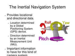
Inertial Navigation – Aircraft Axes Definition • The three axes of the aircraft are: • The roll axis which is roughly parallel to the line joining the nose and the tail Positive angle: right wing down • The pitch axis which is roughly parallel to the line joining the wingtipsPositive angle: nose up • The yaw axis is verticalPositive angle: nose to the right
Inertial Navigation – Aircraft Axes Definition ROLL PITCH YAW
Inertial Navigation – Platform Isolation • The platform is isolated from the aircraft rotation by means of a gimbal system • The platform is connected to the first (inner) gimbal by two pivots along the vertical (yaw) axis. This isolates it in the yaw axis • The inner gimbal is the connected to the second gimbal by means of two pivots along the roll axis. This isolates the platform in the roll axis. • The second gimbal is connected to the INU (Inertial Navigation Unit) chassis by means of two pivots along the pitch axis. This isolates it in the pitch axis.
Inertial Navigation – Platform Isolation Now the platform can be completely isolated from the aircraft rotations
Inertial Navigation – Gyroscopes • To keep the platform level we must be able to: • Sense platform rotation and • Correct for it • To do this we mount gyroscopes on the stable platform and install small motors at each of the gimbal pivots. • The gyroscopes sense platform rotation in any of the three axes and then send a correction signal to the pivot motors which then rotates the relevant gimbal to maintain the platform at the correct attitude
Inertial Navigation – Alignment • Before the INS can navigate it must do two things: • Orient the platform perpendicular to the gravity vector • Determine the direction of True North • Also it must be given: • Initial Position: Input by the Pilot (or navigation computer) • Velocity: This is always zero for commercial systems
Inertial Navigation – Orientation • In the alignment mode the INU uses the accelerometers to send commands to the pivot motors to orient the platform so that the output of the accelerometers is zero. • Note that the earth (and therefore the INU) is rotating so that it will be necessary to rotate the platform in order to keep it level.
Inertial Navigation – Gyrocompassing • The rotation of the platform to keep it level is used to determine the direction of True North relative to the platform heading.
Inertial Navigation – Gyrocompassing The platform is being rotated around the X and Y axes at measured rates: RX=ΩcosΦcosα RY=ΩcosΦsinα Since Ω is known (15.05107 º/hour) we have two equations in two unknowns and can calculate Φ (Latitude) and α (platform heading)
Inertial Navigation – Gyrocompassing The platform is being rotated around the X and Y axes at measured rates: RX=ΩcosΦcosα RY=ΩcosΦsinα Since Ω is known (15.05107 º/hour) we have two equations in two unknowns and can calculate Φ (Latitude) and α (platform heading)
Inertial Navigation – Navigation • Once the INU has been aligned it can be put into NAVIGATE mode . • In navigate mode, the outputs of the accelerometers are used to determine the vehicle’s position and the gyroscopes are used to keep the platform level. • This involves • compensating for the earth’s rotation • compensating for travel over the earth’s (somewhat) spherical surface
Inertial Navigation – Schuler Oscillation To compensate for the travel over the surface of the earth the platform must be rotated by an amount d/R where d is the distance travelled and R is the radius of curvature of the earth R s θ
Inertial Navigation – Schuler Oscillation This leads to a phenomenon know as Schuler oscillation At the end of the alignment procedure the accelerometers are almost never perfectly level.
Inertial Navigation – Schuler Oscillation Assume for now that the aircraft remains at rest The measured acceleration causes the INU to compute a velocity and hence a change in position. This in turn causes the gyros to rotate the platform
Inertial Navigation – Schuler Oscillation Assume for now that the aircraft remains at rest The measured acceleration causes the INU to think that it is moving an it computes a velocity and hence a change in position. This in turn causes the gyros to rotate the platform
Inertial Navigation – Schuler Oscillation The direction of the rotation tends to level the accelerometer but when it is level, the computer has built up a considerable speed and thus overshoots. (this is like pulling a pendulum off centre and letting it go)
Inertial Navigation – Schuler Oscillation Characteristics of the oscillation: a=-gsinθ or –gθ for small angles θ = s/R where R is the radius of curvature differentiating twice
Inertial Navigation – Schuler Oscillation This is a second order differential equation whose solution is: θ = θ0cos(ωt) where θ0 is the initial tilt angle and The period of this oscillation is 84 minutes
Inertial Navigation – Accelerometers • Requirements: • high dynamic range (10-4 g to 10g) • low cross coupling • good linearity • little or no asymmetry • Exacting requirements dictate the use of Force-Rebalance type of devices
Inertial Navigation – Accelerometers • Types: • Pendulum • floating • flexure pivot • Vibrating String or Beam • MEMS (micro electromechanical systems)
Inertial Navigation – Accelerometers Floated Pendulum
Inertial Navigation – Accelerometers Flexure Pivot Pendulum
Inertial Navigation – Accelerometers Vibrating Beam
Inertial Navigation – Gyroscopes • Three main types: • Spinning Mass • Ring Laser • MEMS
Inertial Navigation – Gyroscopes • Spinning Mass: • Rigidity in Space: • A spinning mass has a tendency to maintain its orientation in INERTIAL space • Its rigidity (or resistance to change) depends on its moment of inertia and its angular velocity about the spin axis (INU gyros spin at around 25,000 RPM) • Precession; • If a torque τ is applied perpendicular to the spinning mass it will respond by rotating around an axis 90 degrees to the applied torque. I.e. ω× τ
Inertial Navigation – Gyroscopes Construction:
Inertial Navigation – Gyroscopes • Spinning Mass Gyros: • Disadvantages: • sensitive to shock during installation and handling (Pivots can be damaged) • requires several minutes to get up to speed and temperature • expensive
Inertial Navigation – Gyroscopes • Ring Laser Gyro: (RLG) in service since 1986 • Advantages over spinning mass gyros: • more rugged • inherently digital output • large dynamic range • good linearity • short warm up time
Inertial Navigation – Gyroscopes • Ring Laser Gyro: (RLG) in service since 1986 • General Principle:
Inertial Navigation – Gyroscopes • Ring Laser Gyro: (RLG) in service since 1986 • General Principle:
Inertial Navigation – Gyroscopes • Ring Laser Gyro • Problems: • Lock-in at low rotation rates due to weak coupling between the two resonant systems (coupling due to mirror backscatter) • Analagous to static friction (stiction) in mechanical systems • Causes a dead zone • Alleviated by “dithering” the gyro at a few hundred Hz • Random loss of pulses at the output ( causes “drift”)
Inertial Navigation – Gyroscopes • Fibre Optic Gyro • Similar concept to RLG except that amplification is not usesd • Two strands of optical fibre are wound in opposite directions on a coil form • Laser light is sent from a single source down both fibres • The outputs of the two fibres are combined at a photodiode • Rotation of the coil around its axis causes the two paths to have different lengths and the output of the photodiode provides a light dark pattern. Each cycle indicates an increment of angular rotation
Inertial Navigation – Gyroscopes • Fibre Optic Gyro • Has the advantage of being rugged and relatively cheap • Sensitivity increases with length of fibre • Unfortunately, the longer the fibre, the lower the output signal. • Used on low performance systems
Inertial Navigation – Gyroscopes • MEMS Gyro • All gyros to date have been quite large • in fact the sensitivity of spinning mass gyros and RLGs are a direct function of their size. • Efforts are being made to apply MEMS technology to gyros as well as to accelerometers
MEMS Gyro • The MEMS gyro uses the Coriolis Effect • In a rotating system (such as the earth) moving objects appear to deflected perpendicular to their direction of travel. • The effect is a function of the velocity if the object and the rate of rotation Inertial Navigation – Gyroscopes
Inertial Navigation – Gyroscopes MEMS Gyro In a MEMS gyro the times of a tuning fork are the moving object MEMS gyros exhibit high drift rates and thus are not suitable for commercial aviation use They are used in conjunction with GPS in “coupled” systems which use the best characteristics of each
Inertial Navigation – Strapdown Systems The main problem for an INS is to separate the vehicle acceleration from the effect of gravity on the accelerometers In the stable platform, this is done by maintaining the accelerometers perpedicular to the gravity vector which allows us to ignore the effect of gravity Another approach is to keep track of the gravity vector and subtract its effect from the outputs of the accelerometers This is an analytical or computational implementation
Inertial Navigation – Strapdown Systems As the name implies, the accelerometers are fixed or “strapped down” to the chassis of the INU and hence to the aircraft. Since the gravity vector is three dimensional, three accelerometers are required to keep track of it. In addition, three RLGs are mounted with their axes aligned with the x,y, and z axes (roll, pitch and yaw) of the aircraft respectively.
Inertial Navigation – Strapdown Systems Alignment: During the alignment procedure, the INS measures the direction of the gravity vector. Notice that the outputs of the accelerometers are proportional to the Direction Cosines of the gravity vector
Inertial Navigation – Strapdown Systems Example: If the outputs of the accelerometers are: ax = 0.085773 ay = 0.085773 az = 9.805265 What are the roll and pitch angles?
Inertial Navigation – Strapdown Systems Example: If the roll and pitch angles are Φ and Θ respectively aX = gsin Θ Note: aY = gsin Φcos Θ aZ = gcos Φcos Θ Therefore: Θ=sin-1(aX/g) and Φ= sin-1(aY/gcos Θ)