Download
1 / 5
50 likes | 75 Views
Burraq Engineering Solutions is providing practically electrical courses in Lahore. We offer PLC course, SOLAR SYSTEM Installation and DESIGN COURSE, ETAP course, DIALAX course, Panel FABRICATION course, VFD course, ADVANCED Course Panel, SWITCHERGEAR design course, Building Electrical design course and all electrical diploma courses in Lahore.

E N D
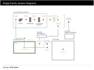
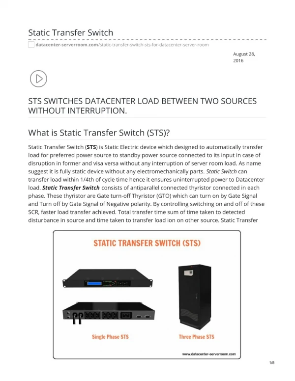
Single Line Diagrams of Automatic Transfer Switch (ATS) Emergency and Standby Power Systems Emergency and backup power systems Backup and standby power systems are typically integrated into the general electrical system for one of two reasons: Single line diagrams of emergency and standby power systems with automatic transfer switch (ATS) (in photo: ATS selects normal power grid or emergency generator; credit: interdc.nl) 1.Legal Requirements - As required by NEC, NFPA 101, NFPA 99, and other local, state, and federal codes and requirements. These relate to the safety of human life, the protection of the environment, etc. 2.Economic Considerations - Continuous process applications often require a continuous power source to avoid significant economic losses. In some cases, even a momentary loss of power can be disastrous. There are different ways of organizing emergency and backup power systems. The most common arrangements are given here. 1.Basic arrangement - radial system 2.More complex systems 3.Hospital arrangements 1. Basic arrangement - radial system
Figure 1 shows the simplest configuration for an uninterruptible or uninterruptible power supply system. It can be recognized as an extension of the single source, transformerless radial system. The transfer switch transfers emergency / standby loads to the AC source in the event of failure of the normal source. This arrangement extends the same inherent weaknesses of the radial system to the emergency system since a single failure of a piece of equipment can result in loss of service for emergency/standby loads. Note that the only generator shown may consist of multiple generator sets operating in parallel, if required. This simple system can be extended to other types of systems such as extended radial systems with: 1 power source and a single main power supply 1 utility source and several main feeders or 2 sources of public services and several primary supplies. 2. More complex systems The basic arrangement of Figure 1 can be extended to other system arrangements. For example, the secondary selection system could be equipped with an emergency system, The emergency/standby charge below the figure will always be supplied by one of the normal sources, if possible, and by the generator (s) otherwise. This will avoid the generator start time for that load in the event of a utility source failure. The two emergency/standby loads in the middle of the figure will be powered from their respective switchboard buses or from the backup source.
Emergency/backup systems are not limited to the low voltage level. For example, the primary / primary / secondary loop selective system can be extended to include an emergency system, 3. Hospital arrangements NFPA 99 and the NEC have very unique requirements for the design of a hospital emergency system. The emergency system is classified under the essential electrical system and the emergency system itself. Electrical system is made up of 'alternative sources of power and all connected distribution systems and ancillary equipment, designed to ensure continuity of electrical supply in designated areas and functions of a health care facility during disturbances of sources of power. 'normal diet, "</ p> An emergency system is “a system of circuits and equipment intended to supply alternating current to a limited number of prescribed functions essential to the protection of life and safety.” The emergency system is part of the essential electrical system. The minimum arrangement, for hospitals of 150 kVA or less, is shown in Figure 4a. The minimum requirement above 150 kVA is shown in Figure 4b. The essential electrical system provides the equipment system, defined as "a system of circuits and equipment arranged for delayed, automatic or manual connection to an emergency power source and serving primarily three-phase power equipment". The backup system provides what is part of the essential electrical system powers the life branch, which is "a subsystem of the emergency system made up of feeders
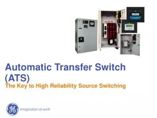
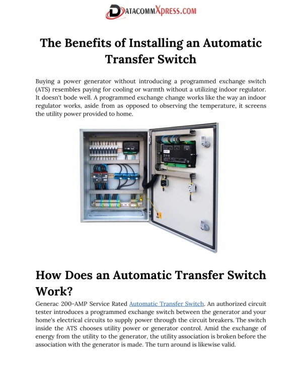
and branch circuits ... intended to provide sufficient power to ensure patient safety. and staff”. The emergency system also supplies the essential branch, which is "a subsystem of the emergency system made up of power lines and circuits providing the energy necessary for the lighting of tasks, special electrical circuits, and selected receptacles serving patient care areas and functions ”. For hospitals of 150 kVA and less, the equipment system, life safety branch, and critical branch can be on the same transfer switch. Note that the transfer switch (s) for the equipment system greater than 150 kVA must be delayed Automatic transfer switch - ATS An automatic transfer switch is defined as "Self-acting equipment capable of transferring one or more load conductor connections from one power source to another". The automatic transfer switch is the most common way to transfer critical loads to uninterruptible/uninterruptible power supply. An automatic transfer switch consists of a switching means and a control system capable of detecting the normal supply voltage and switching to the AC source in the event of failure of the normal source. Automatic transfer switches are available in the nominal values of 30 to 50 A and up to 600V. Because automatic transfer switches are designed to continuously withstand the loads they serve, even under normal conditions, care should be taken to size them to minimize the risk of failure.
Automatic test switches with adjustable sensors, and abort setpoints, and built-in test capability are generally preferred. An automatic transfer switch is generally an open transition device that does not allow the paralleling of the two sources. Manual versions of transfer switches are also available. Burraq Engineering Solutions is providing practically electrical courses in Lahore. We offer a PLC course, SOLAR SYSTEM Installation and DESIGN COURSE, ETAP course, DIALUX course, Panel FABRICATION course, VFD course, ADVANCED Course Panel, SWITCHERGEAR design course, Building Electrical design course and all electrical diploma courses in Lahore.