Download
1 / 60
740 likes | 1.2k Views
Chapter 8: Single-Area OSPF. Routing Protocols. Chapter 8. 8.1 Characteristics of OSPF 8.2 Configuring Single-area OSPFv2 8.3 Configure Single-area OSPFv3. Chapter 8: Objectives. 8.1 Characteristics of OSPF. Open Shortest Path First Evolution of OSPF. Interior Gateway Protocols.

E N D
Chapter 8: Single-Area OSPF Routing Protocols
Chapter 8 8.1 Characteristics of OSPF 8.2 Configuring Single-area OSPFv2 8.3 Configure Single-area OSPFv3
Open Shortest Path FirstEvolution of OSPF Interior Gateway Protocols 1989 updated in 2008 1988
Open Shortest Path FirstComponents of OSPF OSPF Routers Exchange Packets - These packets are used to discover neighboring routers and also to exchange routing information to maintain accurate information about the network.
Open Shortest Path FirstLink-State Operation If a neighbor is present, the OSPF-enabled router attempts to establish a neighbor adjacency with that neighbor
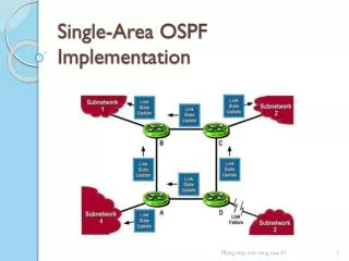
Open Shortest Path FirstLink-State Operation • LSAs contain the state and cost of each directly connected link. • Routers flood their LSAs to adjacent neighbors. • Adjacent neighbors receiving the LSA immediately flood the LSA to other directly connected neighbors, until all routers in the area have all LSAs.
Open Shortest Path FirstLink-State Operation • Build the topology table based on the received LSAs. • This database eventually holds all the information about the topology of the network. • Execute the SPF Algorithm.
Open Shortest Path FirstLink-State Operation From the SPF tree, the best paths are inserted into the routing table.
OSPF MessagesHello Packet • OSPF Type 1 packet = Hello packet • Discover OSPF neighbors and establish neighbor adjacencies • Advertise parameters on which two routers must agree to become neighbors • Elect the Designated Router (DR) and Backup Designated Router (BDR) on multiaccess networks like Ethernet and Frame Relay
OSPF MessagesHello Packet Intervals • OSPF Hello packets are transmitted • To 224.0.0.5 in IPv4 and FF02::5 in IPv6 (all OSPF routers) • Every 10 seconds (default on multiaccess and point-to-point networks) • Every 30 seconds (default on non-broadcast multiaccess [NBMA] networks) • Dead interval is the period that the router waits to receive a Hello packet before declaring the neighbor down • Router floods the LSDB with information about down neighbors out all OSPF enabled interfaces • Cisco’s default is 4 times the Hello interval
OSPF OperationOSPF Operational States • When an OSPF router is initially connected to a network, it attempts to: • Create adjacencies with neighbors • Exchange routing information • Calculate the best routes • Reach convergence • OSPF progresses through several states while attempting to reach convergence.
OSPF OperationEstablish Neighbor Adjacencies DR and BDR election only occurs on multi-access networks such as Ethernet LANs.
Configure Single-area OSPFv2Configuring Passive Interfaces Use the passive-interface router configuration mode command to prevent the transmission of routing messages through a router interface, but still allow that network to be advertised to other routers.
OSPF CostOSPF Metric = Cost Cost = reference bandwidth/ interface bandwidth (default reference bandwidth is 10^8) Cost = 100,000,000 bps / interface bandwidth in bps
OSPF CostOSPF Accumulates Costs Cost of an OSPF route is the accumulated value from one router to the destination network
OSPF CostAdjusting the Reference Bandwidth • Use thecommand - auto-cost reference-bandwidth • Must be configured on every router in the OSPF domain • Notice that the value is expressed in Mb/s: • Gigabit Ethernet - auto-cost reference-bandwidth 1000 • 10 Gigabit Ethernet - auto-cost reference-bandwidth 10000
OSPF CostDefault Interface Bandwidths On Cisco routers, the default bandwidth on most serial interfaces is set to 1.544 Mb/s
OSPF CostManually Setting the OSPF Cost Both the bandwidth interface command and theipospf cost interface command achieve the same result, which is to provide an accurate value for use by OSPF in determining the best route.
Verify OSPFVerify OSPF Neighbors Verify that the router has formed an adjacency with its neighboring routers
OSPFv2 vs. OSPFv3Link-Local Addresses FF02::5 address is the all OSPF router address FF02::6 is the DR/BDR multicast address
Configuring OSFPv3Link-Local Addresses • Link-local addresses are automatically created when an IPv6 global unicast address is assigned to the interface (required). • Global unicast addresses are not required. • Cisco routers create the link-local address using FE80::/10 prefix and the EUI-64 process unless the router is configured manually, • EUI-64 involves using the 48-bit Ethernet MAC address, inserting FFFE in the middle and flipping the seventh bit. For serial interfaces, Cisco uses the MAC address of an Ethernet interface. • Notice in the figure that all three interfaces are using the same link-local address.
Configuring OSFPv3Assigning Link-Local Addresses Configuring the link-local address provides the ability to create an address that is recognizable and easier to remember