Download
1 / 71
720 likes | 920 Views
OSPF (Single Area OSPF). Routing Protocols and Concepts – Chapter 11 Modified by Mike Haines. 07/01/2010. Introduction. In this chapter, you will learn basic, single-area OSPF implementations and configurations.

E N D
OSPF (Single Area OSPF) Routing Protocols and Concepts – Chapter 11 Modified by Mike Haines 07/01/2010
Introduction • In this chapter, you will learn basic, single-area OSPF implementations and configurations. • More complex OSPF configurations and concepts (multi-areas OSPF) are reserved for CCNP-level courses.
Introduction to OSPF Background of OSPF • Began in 1987 • 1989 OSPFv1 released in RFC 1131 This version was experimental & never deployed • 1991 OSPFv2 released in RFC 1247 • 1998 OSPFv2 updated in RFC 2328 • 1999 OSPFv3 published in RFC 2740
Introduction to OSPF OSPF Message Encapsulation • OSPF packet type • There exist 5 types (next slide) • OSPF packet header • Contains - Router ID an area ID and Type code for OSPF packet type • IP packet header • Contains - Source IP address, Destination IP address, & Protocol field set to 89. the destination address is set to one of two multicast addresses: 224.0.0.5 or 224.0.0.6. • Data Link Frame Header • Contains - destination MAC address is also a multicast address: 01-00-5E-00-00-05 or 01-00-5E-00-00-06.
Introduction to OSPF 5 OSPF Packet Types: • 1. Hello - Hello packets are used to establish and maintain adjacency with other OSPF routers. • 2. DBD - The Database Description (DBD) packet contains an abbreviated list of the sending router's link-state database and is used by receiving routers to check against the local link-state database. • 3. LSR - Receiving routers can then request more information about any entry in the DBD by sending a Link-State Request (LSR). • 4. LSU - Link-State Update (LSU) packets are used to reply to LSRs as well as to announce new information. • LSUs contain 7 different types of Link-State Advertisements (LSAs). • LSUs and LSAs are discussed in a later topic. • 5. LSAck - When an LSU is received, the router sends a Link-State Acknowledgement (LSAck) to confirm receipt of the LSU.
OSPF: Hello Protocol • Purpose of Hello Packet • Discover OSPF neighbors & establish adjacencies • Advertise parameters on which routers must agree to become neighbors • Used by multi-access networks to elect a Designated Router and a Backup Designated Router • Type: OSPF Packet Type: Hello (1), DD (2), LS Request (3), LS Update (4), LS ACK (5) • Router ID: ID of the originating router • Area ID: area from which the packet originated • Network Mask: Subnet mask associated with the sending interface • Hello Interval: number of seconds between the sending router's hellos • Router Priority: Used in DR/BDR election (discussed later) • Designated Router (DR): Router ID of the DR, if any • Backup Designated Router (BDR): Router ID of the BDR, if any • List of Neighbors: lists the OSPF Router ID of the neighboring router(s)
OSPF: Hello Protocol Also need to have the same Area ID. Why 10 second hello interval communications consider better than the 30 second routing update for RIP? • Establish adjacencies: • They must agree on three values: Hello interval, Dead interval, and network type. • OSPF Hello Intervals • Hello interval indicates how often an OSPF router transmits its Hello packets • Usually multicast (224.0.0.5) for ALLSPFRouters • sent every 10 seconds on multiaccess and point-to-point segments • Sent every 30 seconds for NBMA segments • OSPF Dead Intervals • This is the time that must transpire before the neighbor is considered down • Default time is 4 times the hello interval • For multiaccess and point-to-point segments, this period is 40 seconds. • For NBMA networks, the Dead interval is 120 seconds. • If the Dead interval expires before the routers receive a Hello packet, OSPF will remove that neighbor from its link-state database.
OSPF: Hello Protocol • To reduce the amount of OSPF traffic on multiaccess networks, OSPF elects a Designated Router (DR) and Backup Designated Router (BDR). • Hello protocol packets contain information that is used in electing DR and BDR • The DR is responsible for updating all other OSPF routers (called DROthers) when a change occurs in the multiaccess network. • The BDR monitors the DR and takes over as DR if the current DR fails. • In the figure, R1, R2, and R3 are connected through point-to-point links. Therefore, no DR/BDR election occurs. • The DR/BDR election and processes will be discussed in a later topic and the topology will be changed to a multiaccess network. More detail discussion on the DR, BDR, DROther later. You need to know this for CCNA exam.
Introduction to OSPF OSPF Link-state Updates • Purpose of a Link State Update (LSU) • Used to deliver link state advertisements • Purpose of a Link State Advertisement (LSA) • Contains information about neighbors & path costs • An LSU packet can contain 11 different types of LSAs,
Introduction to OSPF OSPF Algorithm • OSPF routers build & maintain link-state database containing LSA received from other routers • Information found in database is utilized upon execution of Dijkstra SPF algorithm • SPF algorithm used to create SPF tree • SPF tree used to populate routing table
Introduction to OSPF Administrative Distance • Default Administrative Distance for OSPF is 110
Introduction to OSPF • OSPF Authentication • It is good practice to authenticate transmitted routing information. • This is an interface specific configuration • This practice ensures that routers will only accept routing information from other routers that have been configured with the same password or authentication information MD5 authentication uses a key ID that allows the router to reference multiple passwords, making password migration easier and more secure. Note: Authentication does not encrypt the router's routing table. ?
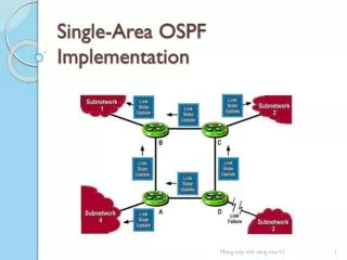
Basic OSPF Configuration Lab Topology • Topology used for this chapter • Discontiguous IP addressing scheme • Since OSPF is a classless routing protocol the subnet mask is will be configured as part of our OSPF configuration.
Basic OSPF Configuration The router ospf command • To enable OSPF on a router use the following command R1(config)#router ospf process-id Process id • A locally significant number between 1 and 65535 ID cannot be 0
Basic OSPF Configuration • OSPF network command • Requires entering: • network address • wildcard mask- the inverse of the subnet mask • area-id - area-id refers to the OSPF area. OSPF area is a group of routers that share link state information Router(config-router)#networknetwork-address wildcard-ask areaarea-id 255.255.255.255 - 255.255.255.240 -------------------- 0. 0. 0. 15 Subtract the subnet mask Wildcard mask 255.255.255.255 - 255.255.255.252 -------------------- 0. 0. 0. 03 Subtract the subnet mask Wildcard mask
Basic OSPF Configuration • Cisco IOS now properly handles overlapping network ... area configuration commands. • Consider the following example: fw#conf t Enter configuration commands, one per line. End with CNTL/Z. fw(config)#router ospf 100 fw(config-router)#network 0.0.0.0 255.255.255.255 area 0 fw(config-router)#network 10.0.0.0 0.0.3.255 area 1 13:06:57: %OSPF-6-AREACHG: 10.0.0.0 255.255.252.0 changed from area 0 to area 1 fw(config-router)#network 10.0.0.0 0.0.0.7 area 2 13:07:10: %OSPF-6-AREACHG: 10.0.0.0 255.255.255.248 changed from area 1 to area 2 fw(config-router)#^Z • I've entered overlapping network statements, each one with a smaller address range. Not only does IOS detect that they overlap, it also prints nice syslog messages and reorders the commands in the running configuration. Well done ! fw#show run | begin router ospf router ospf 100 log-adjacency-changes network 10.0.0.0 0.0.0.7 area 2 network 10.0.0.0 0.0.3.255 area 1 network 0.0.0.0 255.255.255.255 area 0 http://blog.ioshints.info/2006/11/network-statements-in-ospf-process-are.html
Basic OSPF Configuration • ospf network definition for adding all interfaces / default route What’s the difference? router ospf 1 network 0.0.0.0 0.0.0.0 area 0 vs. router ospf 1 network 0.0.0.0 255.255.255.255 area 0 • Both add all existing interfaces into area 0 and all later added interfaces also. Both statements are valid. http://blog.sazza.de/?p=427
Basic OSPF Configuration • Area area-id • An OSPF area is a group of routers that share link-state information. • In this chapter, we will configure all of the OSPF routers within a single area. This is known as single-area OSPF. • Multi-area OSPF is covered in CCNP.
Basic OSPF Configuration • Router ID • This is an IP address used to identify a router • 3 criteria for deriving the router ID 1. Use IP address configured with OSPF router-id command -Takes precedence over loopback and physical interface addresses 2. If router-id command not used then router chooses highest IP address of any loopback interfaces • If no loopback interfaces are configured then the highest IP address on any active physical interface is used • The interface does not need to be enabled for OSPF, meaning that it does not need to be included in one of the OSPF network commands. • However, the interface must be active - it must be in the up state. However!!!!!!
Basic OSPF Configuration • Router ID • If you are the king when the kingdom is built, you are the KING for life • It means when ID is elected, it is the ID for the router, unless …………..
Basic OSPF Configuration OSPF Router ID • Commands used to verify current router ID • Show ip protocols • Show ip ospf • Show ip ospf interface
Basic OSPF Configuration OSPF Router ID • Router ID (not configured) & Loopback addresses (configured) • Highest loopback address will be used as router ID • Advantage of using loopback address the loopback interface cannot fail OSPF stability • The OSPF router-id command • Introduced in IOS 12.0 • OSPF router-id command, which is a fairly recent addition to IOS, it is more common to find loopback addresses used for configuring OSPF router IDs. • Command syntax • Router(config)#router ospf process-id • Router(config-router)#router-id ip-address • Modifying the Router ID • Use the commandRouter#clear ipospf process This command does not work in PT.
Basic OSPF Configuration Modifying the Router ID • The router ID is selected when OSPF is configured with its first OSPF network command. • If the OSPF router-id command or the loopback address is configured after the OSPF network command, the router ID will be derived from the interface with the highest active IP address. • Modifying the Router ID The router ID can be modified with • the IP address from a subsequent OSPF router-id command by reloading the router or • by using the following command: Router#clear ip ospf process • Modifying a router ID with a new loopback or physical interface IP address may require reloading the router
Basic OSPF Configuration Duplicate Router IDs • When two routers have the same router ID in an OSPF domain, routing may not function properly. • If the router ID is the same on two neighboring routers, the neighbor establishment may not occur. • When duplicate OSPF router IDs occur, IOS will display a message similar to: • %OSPF-4-DUP_RTRID1: Detected router with duplicate router ID • To correct this problem, configure all routers so that they have unique OSPF router IDs. • Because some IOS versions do not support the router-id command, we will use the loopback address method for assigning router IDs.
Quick Review We just went over 3 different types of ID • ospf process-id. • OSPF process. • Cannot be 0 • Area ID: • OFPS area • If it is the first, and the backbone area, it is 0 • Router ID • Router ID • 1 IP address is elected per router, • Highest physical address (or) • Highest logical address (loopback)
Basic OSPF Configuration Verifying OSPF • Use the show ip ospf command to verify & trouble shoot OSPF networks: • Neighbor adjacency • Adjacency indicated by • The OSPF state of the interface is “full state” • No adjacency indicated by - • Neighboring router’s Router ID is not displayed • A state of full is not displayed -Consequence of no adjacency- • No link state information exchanged • Inaccurate SPF trees & routing tables • Neighbor ID - The router ID of the neighboring router. • Pri - The OSPF priority of the interface.. • State - The OSPF state of the interface. FULL state means that the router and its neighbor have identical OSPF link-state databases. • Dead Time - The amount of time remaining that the router will wait to receive an OSPF Hello packet from the neighbor before declaring the neighbor down. This value is reset when the interface receives a Hello packet. • Address - The IP address of the neighbor's interface to which this router is directly connected. • Interface - The interface on which this router has formed adjacency with the neighbor.
Basic OSPF Configuration Note: • On multiaccess networks such as Ethernet, two routers that are adjacent may have their states displayed as 2WAY. • This will be discussed in a DR and BDR section. • Two routers may not form an OSPF adjacency if: • The subnet masks do not match, causing the routers to be on separate networks. • OSPF Hello or Dead Timers do not match. • OSPF Network Types do not match. • There is a missing or incorrect OSPF network command. • Neighbor ID - The router ID of the neighboring router. • Pri - The OSPF priority of the interface.. • State - The OSPF state of the interface. FULL state means that the router and its neighbor have identical OSPF link-state databases. • Dead Time - The amount of time remaining that the router will wait to receive an OSPF Hello packet from the neighbor before declaring the neighbor down. This value is reset when the interface receives a Hello packet. • Address - The IP address of the neighbor's interface to which this router is directly connected. • Interface - The interface on which this router has formed adjacency with the neighbor.
Verifying OSPF • Show ip protocols • OSPF process ID, • the router ID, • networks the router is advertising, • the default administrative distance, 110 for OSPF. • Show ip ospf • OSPF process ID • router ID. • OSPF area information • the last time the SPF algorithm was calculated. • R1 has participated in during the past 11 and a half hours is to send small Hello packets to its neighbors. • SPF schedule delay • The router waits 5000 msecs after receiving an LSU before running the SPF algorithm. • There is an additional Hold Time of 10000 msecs between 2 SPF calculations. • Show ip ospf interface • The quickest way to verify Hello and Dead intervals • for OSPF routers to become neighbors, their OSPF Hello and Dead intervals must be identical.
Configuring OSPF loopback address and router priority The command show ip ospf interface will display the interface priority value as well as other key information.
Basic OSPF Configuration Examining the routing table • Use the show ip route command to display the routing table -An “O’ at the beginning of a route indicates that the router source is OSPF -OSPF does not automatically summarize at major network boundaries • Loopback interface counts as a network. • These loopback interfaces are not advertised in OSPF. • They function as router ID.
OSPF Metric • OSPF uses cost as the metric for determining the best route • A cost is associated with the output side of each router interface. • The lower the cost, the more likely the interface is to be used to forward data traffic • The Cisco IOS uses the cumulative bandwidths of the outgoing interfaces from the router to the destination network as the cost value. -Cost is based on bandwidth of an interface • Cost is calculated using the formula 108 / bandwidth -Reference bandwidth • The 100Mbps (FastEthernet) and higher will have the same OSPF cost of 1. • This reference bandwidth can be modified using • auto-cost reference-bandwidth command
OSPF Metric • COST of an OSPF route is the accumulated value from one router to the destination network • For example, in the figure, the routing table on R1 shows a cost of 65 to reach the 10.10.10.0/24 network on R2. • Because 10.10.10.0/24 is attached to a FastEthernet interface, R2 assigns the value 1 as the cost for 10.10.10.0/24. • R1 then adds the additional cost value of 64 to send data across the default T1 link between R1 and R2. 64 + 1 = 65
OSPF Metric • Sometimes the actual speed of a link is different than the default bandwidth • This makes it imperative that the bandwidth value reflects link’s actual speed • Reason: so routing table has best path information • The show interface command will display interface’s bandwidth • Most serial link default to 1.544Mbps • However, some serial interfaces may default to 128 kbps.
Modifying OSPF cost metric • OSPF uses cost as the metric for determining the best route. Cost is calculated using the formula 108/bandwidth, where bandwidth is expressed in bps. (Cost = 100,000,000/Bandwidth) • The Cisco IOS automatically determines cost based on the bandwidth of the interface. • It is essential for proper OSPF operation that the correct interface bandwidth is set. Router(config)#interface serial 0/0Router(config-if)#bandwidth 64 The default bandwidth for Cisco serial interfaces is 1.544 Mbps, or 1544 kbps. COD has these 2 types of serial cards in the lab 2A/S 2T
OSPF Metric: Bandwidth • Remember, this bandwidth value does not actually affect the speed of the link; it is used by some routing protocols to compute the routing metric. • It is important that the bandwidth value reflect the actual speed of the link so that the routing table has accurate best path information. • The figure displays the routing table for R1. • R1 believes that both of its serial interfaces are connected to T1 links, • one of the links is a 64 kbps link • the other one is a 256 kbps link. • This results in R1's routing table having two equal-cost paths to the 192.168.8.0/30 network, when Serial 0/0/1 is actually the better path. How to modify the cost of all the links?
Basic OSPF Configuration Modifying the Cost of a link • Both sides of a serial link should be configured with the same bandwidth • Commands used to modify bandwidth value • Bandwidth command • Example: Router(config-if)#bandwidthbandwidth-kbps • ip ospf cost command – allows you to directly specify interface cost -Example:R1(config)#interface serial 0/0/0 R1(config-if)#ip ospf cost 1562
Modifying the Cost of the link • Difference between bandwidth command & the ip ospf cost command • Ip ospf cost command • Sets cost to a specific value • Bandwidth command • Link cost is calculated
OSPF and Multiaccess Networks Challenges in Multiaccess Networks • OSPF defines five network types: • Point-to-point • network there are only two devices on the network, one at each end. • Broadcast Multiaccess • a network with more than two devices on the same shared media. • all devices on the network see all broadcast frames. • Nonbroadcast Multiaccess (NBMA) • networks include Frame Relay, ATM, and X.25 networks. • Point-to-multipoint • networks include Frame Relay, ATM, and X.25 networks. • Virtual links • Virtual links are a special type of link that can be used in multi-area OSPF.
OSPF in Multiaccess Networks • 2 challenges presented by multiaccess networks • Multiple adjacencies • Extensive LSA flooding • The creation of an adjacency between every pair of routers in a network would create an unnecessary number of adjacencies. • This would lead to an excessive number of LSAs passing between routers on the same network. • 5 routers in the figure will need 10 adjacencies, • 10 routers would require 45 adjacencies. • 20 routers would require 190 adjacencies
OSPF in Multiaccess Networks • Extensive flooding of LSAs For every LSA sent out there must be an acknowledgement of receipt sent back to transmitting router. consequence: lots of bandwidth consumed and chaotic traffic Solution:
Steps in the operation of OSPF • OSPF routers send Hello packets on OSPF enabled interfaces. • On multi-access networks, the routers elect a DR and BDR. On these networks other routers become adjacent to the DR. To reduce the number of adjacencies traffics To reduce the number of adjacencies each router must form, OSPF calls one of the routers the designated router. A designated router is elected as routers are forming adjacencies, and then all other routers establish adjacencies only with the designated router. This simplifies the routing table update procedure and reduces the number of link-state records in the database. The designated router plays other important roles as well to reduce the overhead of a OSPF link-state procedures. For example, other routers send link-state advertisements it to the designated router only by using the all-designated-routers multicast address of 224.0.0.6. http://www.chebucto.ns.ca/Chebucto/Technical/Manuals/Max/max6000/isptele/maxospf.htm
Steps in the operation of OSPF • OSPF routers send Hello packets on OSPF enabled interfaces. • On multi-access networks, the routers elect a DR and BDR. On these networks other routers become adjacent to the DR.
Steps in the operation of OSPF • To reduce the number of adjacencies traffics http://www.cisco.com/warp/public/104/11.html
OSPF in Multiaccess Networks • Solution to LSA flooding issue is the use of • Designated router (DR) • Backup designated router (BDR) • this solution is analogous to electing someone in the room to go around and learn everyone's names and then announce these names to everyone in the room at once. • DROther • All other routers become DROthers (this indicates a router that is neither the DR or the BDR). • DROthers only form full adjacencies with the DR and BDR in the network. • DR & BDR • On multiaccess networks, OSPF elects a Designated Router (DR) to be the collection and distribution point for LSAs sent and received. • A Backup Designated Router (BDR) is also elected in case the Designated Router fails. • DR & BDR are elected to send & receive LSA
OSPF in Multiaccess Networks • DR & BDR & DROther • Routers on a multiaccess network elect a DR and BDR. • DR & BDR are elected to send & receive LSA • DROthers only form full adjacencies with the DR and BDR in the network. • Sending & Receiving LSA • DRothers send LSAs via multicast 224.0.0.6 to DR & BDR (ALLDRouters - All DR routers) • DR forward LSA via multicast address 224.0.0.5 to all other routers (AllSPFRouters - All OSPF routers).
OSPF in Multiaccess Networks DR/BDR Election Process • DR/BDR elections DO NOT occur in point-to-point networks • DR/BDR elections will take place on multiaccess networks as shown below
OSPF in Multiaccess Networks • Criteria for getting elected DR/BDR • DR: Router with the highest OSPF interface priority. 2. BDR: Router with the second highest OSPF interface priority. 3. If OSPF interface priorities are equal, the highest router ID is used to break the tie.
Criteria for getting elected DR/BDR • DR: Router with the highest OSPF interface priority. 2. BDR: Router with the second highest OSPF interface priority. 3. If OSPF interface priorities are equal, the highest router ID is used to break the tie. • Example: • The OSPF for all interface priority is 1. • The OSPF router ID is used to elect the DR and BDR. • RouterC with the highest router ID, becomes the DR • RouterB, with the second highest router ID, becomes the BDR. • Because RouterA is not elected as either the DR or BDR, it becomes the DROther. DROthers only form FULL adjacencies with the DR and BDR, but will still form a neighbor adjacency with any DROthers that join the network. When two DROther routers form a neighbor adjacency, the neighbor state is displayed as 2WAY. You need 4 routers topology to see this “2way” adjacency.
OSPF network types (cont.) • RealDR and BDR election process The first router up on the network is the DR. The second router up on the network is the BDR. If the DR fails then the BDR becomes DR and another router is elected the BDR. The DR does not change just because another router comes on line with a higher priority or a higher router id. If both the existing DR and BDR fail and a new DR must be elected, the router with the highest priority is elected DR. If there's a tie, the router with the highest router id is elected DR.
Timing of DR/BDR Election (This is really of how the election works) • Election occurs as soon as 1st router has its OSPF enabled on multiaccess network. This can happen when 1. When the routers are powered-on • it is possible that a router with a lower router ID will become the DR. This could be a lower-end router that took less time to boot. 2. when the OSPF network command for that interface is configured. • When a DR is elected it remains as the DR until one of the following occurs -The DR fails. -The OSPF process on the DR fails. -The multiaccess interface on the DR fails.