Download
1 / 8
80 likes | 220 Views
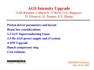
H – Stripping Foil. Target. 200-MeV DTL. 1.0-GeV FFAG. Acceleration. Filling. 1.0-GeV 10-MWatt Proton Driver. Injection Energy, U i 200 MeV Extraction Energy, U f 1.0 GeV Beam Ave. Power, P = I U f 10.0 MWatt Repetition Rate, F 1.0 kHz

E N D
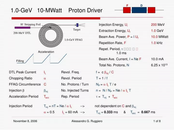
H– Stripping Foil Target 200-MeV DTL 1.0-GeV FFAG Acceleration Filling 1.0-GeV 10-MWatt Proton Driver Injection Energy, Ui200 MeV Extraction Energy, Uf1.0 GeV Beam Ave. Power, P = IUf10.0 MWatt Repetition Rate, F1.0 kHz Repet. Period, 1.0 ms Beam Ave. Current, I = Ne F 10.0 mA Total No. Protons, N 6.25 x 10¹³ DTL Peak Current IL Revol. Freq. f = c inj / C Chopping Ratio Revol. Period T = 1 / f FFAG Circumference C No. Protons / Turn NP= ILT / e Injection injNo. Injected Turns n = N / NP = Ne / IL T Acceleration Period Tacc Rep. Period = Tinj + Tacc Injection Period Tinj= nT = Ne / IL --> not dependent on C and inj = 0.5 IL = 60 mA--> Tinj = 0.333 ms & Tacc = 0.667 ms Alessandro G. Ruggiero
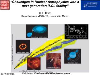
General Beam- RF Considerations Average Energy Gain / Turn W No. Revol. Acceleration Period m = (Uf – Ui) / W Average Revol. Period Tave = C /ave c Acceleration Period Tacc = m Tave = Tave (1 – Ui / Uf) (1 + ) Uf / W extra acceleration time dilation factor (1 – Ui / Uf) (1 + ) ~ 1 Uf = P / Ne Acceleration Period Tacc = Tave P / Ne W Cycle Period = Tinj + Tacc = Tinj / (1 – P / PB) Average Beam Accel. Power PB = W N e / Tave PB = (3 / 2) P = 15 MWatt Average RF Power PRF = PB + Pcavity = 2 PB = 30 Mwatt FFAG Cycle Efficiency P / PRF = 33% or P / PAC = 25% Energy Gain / Unit Length W / C = (5.0 / ave) keV /m Alessandro G. Ruggiero
More on RF Acceleration System • FFAG Circumference C = 201.8 m • ave = 0.75 • Energy Gain W = 1.35 MeV / Turn • RF Peak Voltage VRF = 1.8 Mvolt • Harmonic Number h = 36 • No. Empty Buckets 9 out of 36 • Protons / Bunch 2.4 x 10¹² • No. of RF Cavities 40 • No. of Gaps / Cavity 1 • Cavity Length 1 m • Peak RF Voltage / Gap 45 kVolt • Power Amplifier / Cavity 0.8 MWatt • Cavity Inter. Diameter 10 cm 25 MHZ / ms Issue # 1 Can the RF ferrite be swept in 2/3 ms ? Energy Range, MeV 2001,000 0.566 0.875 Rev. Frequency, MHz 0.841 1.300 Revolution Period, µs 1.189 0.769 RF Frequency, MHz 30.28 46.80 Peak Current, Amp 12.65 19.55 Peak Beam Power, MW 15.2 23.5 Alessandro G. Ruggiero
Diagnostic & Steering Boxes Flanges & Bellows D-Sector Magnet 20 cm Top View Vacuum Pump F-Sector Magnets Diagnostic & Steering Boxes Flanges & Bellows D-Sector Magnet 10 cm Side View Diagnostic & Steering Boxes Vacuum Pump F-Sector Magnets D-Sector Magnet RF Cavity Vacuum Pump F-Sector Magnets Period Layout (68 Cells) 0 m 1.0 m 2.0 m 3.0 m 100 k$ 600 k$ Alessandro G. Ruggiero
Circulating Beam 20 x 20 mm Foil Injected Beam 1.0 GeV 200 MeV 10 cm x 20 cm Vacuum Chamber B1 Injection Orbit B2 Bump Orbit C1 Foil C2 From DTL Multi-Turn Injection (H–) Linac Peak Current 60 mA Revolution Period 1.89 µs No. of Protons / FFAG pulse 6.25 x 10¹³ Chopping Ratio 0.50 Chopping Frequency 30.283 MHz Single Pulse Length 0.333 ms No. of Turns Injected / pulse 165 Linac/FFAG Rep. Rate 1.0 kHz Linac Duty Cycle 0.33 % Linac Beam Emittance, rms norm. 1 π mm-mrad Final Beam Emittance, full norm. 150 π mm-mrad Bunching Factor 3 Space-Charge Tune-Shift 0.35 Alessandro G. Ruggiero
Kicker Septum F D F F D F F D F Single-Turn Extraction Revolution Period 1.89 µs Beam Gap 330 ns Kicker Magnet, Length 1.0 m Field 1 kG Rise-Time < 300 ns Septum Magnet, Length 1.0 m Field 10 kG Repetition Rate 1.0 kHz The Kicker field remains constant for the duration of the beam pulse (about 1.6 µs), and it is finally reset to zero-value in about 1.0 ms, to be fired again the next cycle. Alessandro G. Ruggiero
hi Bi(xco) (tan xco') y Bi (1 + ) y' = – x, cm Half Period 1 GeV D F xco xco' 200 MeV s, m Rule #4 for the FFAG Design Make FFAG Circumference as large as possible Chose a number as large as possible of Periods Avoid the Curvature effect at Low Energy small Rings x + h2 x / (1 + ) + h2 n y / (1 + ) = h / (1 + ) y – h2 n y / (1 + ) = 0 To keep small Tune Variation with the AFP minimize the Edge Effects Vertical == Focusing Horizontal == Defocusing Alessandro G. Ruggiero
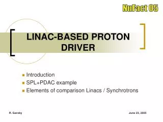
H– Stripping Foil Target 200-MeV DTL 1.0-GeV FFAG AC Power Sub-critical Fissionable material Experimental Areas: Spallation Neutrons Waste Transmutation Tritium Production Radio-Isothops Production Exotic Elements Production, ….. Conclusions FFAG Proton Accelerators are a very promising alternative to other Accelerator Architectures (Super-Conducting Linacs, Cyclotrons, Rapid Cycling Synchrotrons), especially in view of the recent progress in beam dynamics and of new proposed design approaches. FFAG’s rely on conventional Magnet Technology, thus appealing to many centers of research. They are supposed to be less expensive: a crude estimate of the Proton Driver described here shows a cost of about 50M$ (excluding DTL and Tunnels). In the case of Protons, the Path Length variation with Momentum is not a concern if there is at any time only a single beam pulse circulating. A 10 MWatt beam power requires a AC source of about 40-50 MWatt. It is then imperative to demonstrate methods to create energy with the use of sub-critical nuclear material. The next step is to resolve the 2 main Issues Alessandro G. Ruggiero