Download
1 / 33
330 likes | 502 Views
FLRP: Proton Driver. Bob Kephart March 11, 2004. Outline. FLRP: Proton Driver Working Group Proton Driver Design Studies 8-GeV synchrotron 8-GeV Superconducting Linac bulk of the talk MI upgrades FLRP: PD recommendations Conclusions. Studies of the FNAL Proton Source.

E N D
FLRP: Proton Driver Bob Kephart March 11, 2004
Outline • FLRP: Proton Driver Working Group • Proton Driver Design Studies • 8-GeV synchrotron • 8-GeV Superconducting Linac bulk of the talk • MI upgrades • FLRP: PD recommendations • Conclusions FLRP Presentation:Proton Driver
Studies of the FNAL Proton Source • Several studies have had the goal of understanding the limitations of the existing source and suggesting upgrades • Proton Driver Design Study I: • 16 GeV Synchrotron (TM 2136) Dec 2000 • Proton Driver Design Study II (draft TM 2169) : • 8 GeV Synchrotron May 2002 • 2 MW upgrade to Main Injector May 2002 • 8 GeV Superconducting Linac: Feb 2004 • Proton Team Report (D Finley):Oct 2003 • Report: http://www.fnal.gov/directorate/program_planning/studies/ProtonReport.pdf • Limitations of existing source, upgrades for a few 10’s of $ M. • “On the longer term the proton demands of the neutrino program will exceed what reasonable upgrades of the present Booster and Linac can accommodate FNAL needs a plan to replace its aging LINAC & Booster with a new more intense proton source (AKA aProton Driver) FLRP Presentation:Proton Driver
Fermilab:Long Range Planning • In April of 2003 the Fermilab Director formed a committee to provide advice on the long range scientific program of the laboratory. FLRP Membership & Charge: http://www.fnal.gov/directorate/Longrange/Long_rang_planning.html • Excerpt from the charge to the LRP committee: “ I would like the Long-range Planning Committee to develop in detail a few realistically achievable options for the Fermilab program in the next decade under each possible outcome for the linear collider. ….“ • It was clear from the start that a new intense proton source to serve long baseline neutrino experiments was one such option… FLRP Presentation:Proton Driver
FLRP:PD Working group PD Subcommittee: Bob Kephart, chair Steve Geer Chris Hill Peter Meyers Sergei Nagaitsev Technical Advisors Dave Finley Past BD Head (proton economics) John Marriner Past BD Head Shekar Mishra Past deputy head MI project Victor Yarba SCRF R&D (started TD RF group) Proponents Weiren Chou Synchrotron based Proton Driver Bill Foster SCRF Linac based Proton Driver FLRP Presentation:Proton Driver
FLRP:PD Working group • Had a series of 14 meetings • Well attended by Expert Participants • 27 additional people made presentations or important contributions to the meetings • 3 joint meetings with other LRP sub committees • To obtain input from the community an open session took place on Oct 9, 2003 • “FLRP Retreat” Jan 9-10 • “Draft Proton Driver Recommendations • Final Report and recommendations in Mar 2004 • PD meetings has now evolved into a regular Proton Driver R&D/Design meeting • More people joining the effort FLRP Presentation:Proton Driver
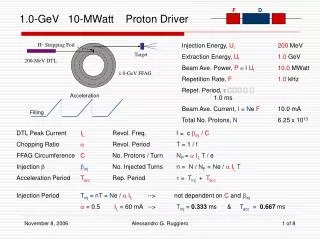
Proton Driver Design Studies • 8 GeV Synchrotron (TM 2169) • Basic plan is to replace the existing Booster with a new large aperture 8 GeV Booster (also cycling at 15 Hz) • Takes full advantage of the large aperture of the Main Injector • Goal= 5 times # protons/cycle in the MI ( 3 x 10131.5 x 1014 ) • Reduces the 120 GeV MI cycle time 20% from 1.87 sec to 1.53 sec • The plan also includes improvements to the existing linac (new RFQ and 10 MeV tank) and increasing the linac energy (400600 MeV) • The increased number of protons and shorter cycle time requires substantial upgrades to the Main Injector RF system • Net result = increase the Main Injector beam power at 120 GeV by a factor of 6 (from 0.3 MW to 1.9 MW) FLRP Presentation:Proton Driver
PD: 8 GeV Synchrotron • Sited West of the existing booster • Twice the shielding of the current booster • Large aperture magnets • Collimators contain losses to avoid activation of equipment FLRP Presentation:Proton Driver
PD: 8 GeV Synchrotron • Synchrotron technology well understood • May be cheaper than an 8 GeV linac • We have more experience with this kind of machine • But… • Doesn’t replace entire linac 200 MHz PA’s would still be a vulnerability, aging linac equipment still an issue • Cycle time is still 15 Hz it would still take 5/15 of a sec to fill MI with 6 booster batches limits upgrades to the MI cycle time (Beam power is proportional to # p/cycle x cycles/sec) • Large aperture rapid cycling magnetsdevelopment • Significant interruption of operations to upgrade linac and break into various enclosures (vs Run II) • Losses, instabilities, etc… vs ultimate performance ? FLRP Presentation:Proton Driver
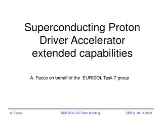
PD: 8 GeV SC Linac • Basic concept, design, (& slides) are due to Bill Foster at FNAL • Observation: $/ GeV for SCRF has fallen dramatically can consider a solution in which H- beam is accelerated to 8 GeV in a SC linac and injected directly into the Main Injector • Why an SCRF Linac looks attractive: • Many components exist (few parts to design vs new booster synchrotron) • Copy SNS, RIA, & AccSys Linac up to 1.2 GeV • Use “TESLA” Cryo modules from 1.2 8 GeV • Probably simpler to operate vs two machines (ie linac + booster) • Produces very small emittances vs a synchrotron • Delivers high beam powers simultaneously at 8 & 120 GeV • Injection into MI is done with 90 turns of small transverse emittance beam (2 p mm-mrad, 95% normalized)which is “phase space painted” into MI (40 p ) aperture in 1 ms MI “fill time” that is negligible vs MI ramp times (more later) FLRP Presentation:Proton Driver
8 GeV Linac Siting for Design Study • Sited tangent to the Main Injector FLRP Presentation:Proton Driver
Other Possible SCRF Linac Missions • Principle Mission: Proton superbeams for Neutrinos • 8 GeV or 120 GeV from MI (NUMI/Off-axis) • Also: • Protons for future 120 GeV fixed target experiments and continued anti-proton production • Other possibilities: • Accelerate electrons ? • Could drive an x-ray FEL ? • Could be useful for LC beam or technology studies ? • Spallation Neutron source ? • Low emittance injector to a future VLHC ? FLRP Presentation:Proton Driver
Technological Synergies • Lots of machines use or plan use of SCRF • This provides many opportunities for collaboration and shared infrastructure/development costs • Other Accelerators: • Existing: ATLAS (ANL), CBEAF, FNPL, TTF-I (DESY) • Construction: SNS (ORNL), DESY FEL • Proposed: • Cold Technology Linear Collider (TESLA) • RIA (ANL) • Light sources: LUX (LBNL), Cornell light source, PERL (BNL) • Electron cooling in RHIC (BNL) • eRHIC (BNL) • BNL proton superbeam • Medical isotope production, etc FLRP Presentation:Proton Driver
A Draft Design Study exists • Web Link: http://tdserver1.fnal.gov/project/8GeVLinac/DesignStudy/ 131 page document • Plan: Next Few Weeks: • Merge with PD II Design Study • Technically it looks to be feasible • Principle issue is the cost • SNS was very expensive but there are reasons that this was so… • TESLA appears to be very cheap / Gev • Need to do a careful Technical Design Report including optimization and costs • That’s the plan (more later) FLRP Presentation:Proton Driver
8 GeV Linac BaselineDesign Study (130 pages):http://tdserver1.fnal.gov/project/8gevlinac • Warm Copper DTL • 805 MHz SNS & RIA Cavities to 1.3 GeV • Modified TESLA (1207.5 MHz) to 8 GeV • 48 “TTF-style” Cryomodules • 384 Cavities (assuming TESLA-500 Gradients) New Technology: Extend TESLA RF Fan-Out to Proton/H- Linac • 41 Klystrons in baseline design FLRP Presentation:Proton Driver
Most other TECHNICAL SUBSYSTEM DESIGNS EXIST and have been shown to WORK SNS Cavites FNAL/TTF Modulators “TTF Style” Cryomodules Civil Const. Based on FMI RF Distribution* *requires ferrite phase shifter R&D FLRP Presentation:Proton Driver
TESLA-Style Cryomodules for 8 GeV • Design conceptually similar to TESLA • No large cold gas return pipe • Cryostat diameter ~ LHC • RF Couplers are KEK / SNS design, conductively cooled for 10 Hz operation • Cold string length ~ 300m vs every module in SNS => cheaper (more like TESLA) FLRP Presentation:Proton Driver
8 GeV Linac Baseline 2 MW FLRP Presentation:Proton Driver
8 GeV Linac Parameters FLRP Presentation:Proton Driver
RF System for 1.2 8 GeV Linac • Assumes TESLA-style RF distribution works • One TESLA multi-beam Klystron per ~12 Cavities • Requires a “fast ferrite” E-H tuner to control the phase and amplitude to each cavity • The fundamental technology is proven in phased-array radar transmitters. • This R&D was started by SNS but dropped due to lack of time. • R&D is required to optimize the design for the Linac, funding in TD FY04 budget to start this effort • Also needed if Linac alternates between e and P. • Modulators are identical to TESLA modulators FLRP Presentation:Proton Driver
RF Fanout at Each Cavity FLRP Presentation:Proton Driver
ELECTRONICALLY ADJUSTABLEE-H TUNER Attractive Price Quote from AFT (<< Klystron) FERRITE LOADED SHORTED STUBS CHANGE ELECTRICAL LENGTH DEPENDING ON DC MAGNETIC BIAS. TWO COILS PROVIDE INDEPENDENT PHASE AND AMPLITUDE CONTROL OF CAVITIES FLRP Presentation:Proton Driver
Cost Optimizations & Options • Staging: Extend Klystron Fanout 12:1 36:1 • Drop beam current, extend pulse width • Drop rep. rate & avg. power 2 MW0.5 MW • Consider SCRF Front End (RIA Spokes) • Assume TESLA 800 surface fields will work: • Baseline 5 GeV linac by assuming TESLA 500 gradients, • Deliver 8 GeV linac by achieving TESLA 800 gradients. 384 Cavities 240 cavities ; Linac Length: 650m 400 FLRP Presentation:Proton Driver
Frequency Options • Standardize on SNS / RIA (805 MHz) • Develop “modified TESLA” 1207.5 MHz cavities • Develop Modified Multi-Beam Klystron • Develop new spoke resonator family if SCRF • Standardize on TESLA (1300 MHz) • Develop new family of “TESLA-Compatible” beta<1 cavities • Already 3 vendors for main MBK • Develop new spoke resonator family if SCRF FLRP Presentation:Proton Driver
Main Injector with 8 GeV Linac • H- stripping injection at 8 GeV • 25 mA linac beam current • 90-turn Injection gives MI Beam Current ~2.3 A ( SNS has 1060 turn injection at 1 GeV ) • preserve linac emittances ~2(or even ~0.5 (95%) at low currents) • phase space painting needed at high currents • avoids space charge limitations present at lower energy can put a LOT of beam in MI ! • 1.5 Second Cycle time to 120 GeV • filling time 1 msec or less • no delay for multiple Booster Batches • no beam gaps for “Booster Batches” -- only Abort gap • Even faster MI cycle times can be considered ( x 2 ?) FLRP Presentation:Proton Driver
120 GeV Main Injector Cycle with 8 GeV Synchrotron FLRP Presentation:Proton Driver
120 GeV Main Injector Cycle with 8 GeV Linac, e- and P FLRP Presentation:Proton Driver
Linac Allows Reduced MI Beam Energy without Compromising Beam Power MI cycles to 40 GeV at 2Hz, retains 2 MW MI beam power FLRP Presentation:Proton Driver
Running at Reduced Proton Energy Produces a Cleaner Neutrino Spectrum Running at 40 GeV reduces tail at higher neutrino energies. Same number of events for same beam power may be a useful operating mode (Plot courtesy Fritz & Debbie) FLRP Presentation:Proton Driver
Comparison of PD options • My conclusions: The SCRF Linac PD is more likely to deliver the desired performance, is more “flexible” machine than the synchrotron based PD, and has more “growth” potential FLRP Presentation:Proton Driver
Draft PD Recommendations • We recommend that Fermilab prepare a case sufficient to achieve a statement of mission need (CD-0) for a 2 MW proton source (Proton Driver). We envision this project to be a coordinated combination of upgrades to existing machines and new construction. • We recommend that Fermilab elaborate the physics case for a Proton Driver and develop the design for a superconducting linear accelerator to replace the existing Linac-Booster system. Fermilab should prepare project management documentation including cost & schedule estimates and a plan for the required R&D. Cost & schedule estimates for Proton Driver based on a new booster synchrotron and new linac should be produced for comparison. A Technical Design Report should be prepared for the chosen technology. FLRP Presentation:Proton Driver
CONCLUSIONS • It seems likely that a new intense proton source will be proposed for construction at FNAL in near future • Similar in scope to the Main Injector Project (cost/schedule) • A 8 GeV Synchrotron or a Superconducting Linac appear to be both technically possible. However the SCRF linac has many attractive features if it can be made affordable • The FNAL management will request that the 8 GeV linac design be developed including cost & schedule information so that a technology choice can be made • A Technical Design Report will be developed in the next year for the chosen Technology (charge) • This will make it possible to submit a Proton Driver project to the DOE for approval and funding FLRP Presentation:Proton Driver