Download
1 / 15
150 likes | 318 Views
C&B Technology Inc. DATE : 05. Jun. ‘02 REVISION No. 2.0. MESSRS. APPROVAL SHEET. DESCRIPTION : CCD Color Board Camera. SET MODEL NO. : CNB - EN257, 258, 257C, 258C ( NTSC ) CNB - EP257, 258, 257C, 258C ( PAL ). Receipt Stamp.

E N D
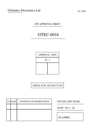
C&B Technology Inc. DATE : 05. Jun. ‘02 REVISION No. 2.0 MESSRS. APPROVAL SHEET DESCRIPTION : CCD Color Board Camera SET MODEL NO. : CNB - EN257, 258, 257C, 258C ( NTSC ) CNB - EP257, 258, 257C, 258C ( PAL ) Receipt Stamp ISSUED CHECKED APPROVED WWW.CNBTEC.COM
C&B Technology Inc. CNB-EN257/257C/258/258C, EP257/257C/258/258C Specifications REVISION CONTENTS NO REVISION CONTENTS REVISION DATE Page REMARKS
C&B Technology Inc. CNB-EN257/257C/258/258C, EP257/257C/258/258C Specifications CCD COLOR BOARD CAMERA CNB – E N 2 5 7 C D 1 2 3 4 N : NTSC P : PAL 1 7 : 32 X 32 8 : 38 X 38 2 C : C/CS MOUNT LENS P : PIN HOLE LENS V : VARI-FOCAL LENS 3 D : DC IRIS 4 CONTENTS PAGE 1. SPECIFICATIONS------------------------------------------------------------ 2 2. MEASUREMENT SPECIFICATIONS------------------------------------ 4 3. ENVIRONMENT CONDITION AND TEST----------------------------- 4 4. INTERFACE------------------------------------------------------------------- 4 5. APPEARANCE---------------------------------------------------------------- 6 6. PACKING METHOD--------------------------------------------------------- 7 1/7
C&B Technology Inc. CNB-EN257/257C/258/258C, EP257/257C/258/258C Specifications 1. SPECIFICATIONS REMARKS Signal System NTSC ( CNB – EN257/258) PAL ( CNB – EP257/258 ) Scanning System 2 : 1 Interlace Scanning Frequency ( H ) 15.734 KHz 15.625 KHz Scanning Frequency ( V ) 59.94 Hz 50 Hz Image Sensor 1 / 3” IT SUPER HAD CCD SONY Total Pixels No. 537 (H) X 505 (V) 270K 537 (H) X 597 (V) 320K Effective Pixels No. 510 (H) X 492 (V) 250K 500 (H) X 582 (V) 290K “ Bold : Default Mode ” 1) Angle of view at Diagonal 88˚ ( f= 3.8 mm ) 60 ˚ ( f= 5.8 mm ) 2) Signal Process Digital Signal Process 3) Sync System Internal 4) Camera Function a) Video Focus Focus free from 0.1m( f= 3.8 mm ) ,0.1m(f= 5.8 mm ) to ∞ • b) White Balance Auto • c) Shutter Speed Auto • d) Iris Control Fixed / DC Iris ( Optional : EN(P)258 ) • e) Gain Control Auto • f) AGC Control ON / OFF ( Optional : EN(P)258 ) • g ) Backlight ON / OFF ( Optional : EN(P)258 ) 5) Video Output Level NTSC Video Level 0.714 ± 0.07V ( 100 ± 10 IRE) Sync Level 0.286 ± 0.035V ( 40 ± 10 IRE) Burst Level 0.286 ± 0.035V ( 40 ± 10 IRE) PAL Video Level 700 ± 70 mV Sync Level 300 ± 35 mV Burst Level 300 ± 35 mV 2/7
C&B Technology Inc. CNB-EN257/257C/258/258C, EP257/257C/258/258C Specifications 6) Color Reproduction COLOR RED BLUE YELLOW BURST NTSC Amplitude ( % ) 177 ± 40 % 136 ± 40 % 115 ± 40 % 118 %(Base) Phase ( ˚ ) 110 ± 20 ˚ 338 ± 20 ˚ 182 ± 20 ˚ 180 ˚ (Base) PAL Amplitude ( % ) 170 ± 40 % 127 ± 40 % 120 ± 40 % 100 %(Base) Phase ( ˚ ) 103 ± 20 ˚ 335 ± 20 ˚ 170 ± 20 ˚ 182 ˚ (Base) 7) Horizontal Resolution More than 380 Lines 9) Sensitivity Typ. 0.1Lux ---- At signal Level 30 IRE ( LENS-F : F = 1.4 ( WIDE ) AGC Gain : Max ) 8) Luminance S/N More than 48dB 10) Supplied Voltage 9.0 V ~ 15.0 V ( Recommendation 12.0 V ± 0.5 V ) 11) Supplied Current 130mA 12) Power consumption 1.6 W (Max) 13) Dimensions 32.0 (W) × 32.0 (H) × 24.0(D) mm : EN/P257 38.0 (W) × 38.0 (H) × 24.0(D) mm : EN/P258 14) Weight 25 g ( Approx. ) 16) Appearance / Dimensions See Attached Page 6. 17) Packing Method See Attached Page 7. 18) Optional Accessories 3 Pin Harness A’Y Y Terminal (P/N : 6810 – 0001A) 3/7
C&B Technology Inc. CNB-EN257/257C/258/258C, EP257/257C/258/258C Specifications 2. MEASUREMENT SPECIFICATIONS * Standard Measurement Condition and Measurement Procedure See an Annexed Document “ APPENDIX 1 ” 3. ENVIRONMENT CONDITION AND TEST 1) Operating Condition Temperature -10 ˚ C ~ 50 ˚ C ( Recommendation : - 5 ˚ C ~ 40 ˚ C ) Humidity 10 % ∼ 85 % 2) Storage Condition Temperature -20 ˚ C ~ 60 ˚ C Humidity 0 % ∼ 90 % 3) High Temperature storage Test Leaving the packed at Temperature of 60 ˚ C for 72 Hours, and after leaving it at Normal Temperature for 8 Hours, there should be no Problem in Performance. 4) Low Temperature storage Test Leaving the packed at Temperature of -20 ˚ C for 72 Hours, and after leaving it at Normal Temperature for 8 Hours, there should be no Problem in Performance. 4. INTERFACE 1) Pin Assignment ( J201, 3 Pin 1.25mm Pitch ; Maker Molex/Yeonho , 12512WS-03A00 ) * is the color of the cable. ( If it offered ) *COLOR PIN No. I/O Note NAME 9 V ~ 15 V ( Recommendation 12±0.5 V ) Red DC IN (ALIVE) Input 1 Black 2 GND (For Video) 3 Yellow 1.0 Vp-p at 75Ω Output VIDEO OUT 4/7
C&B Technology Inc. CNB-EN257/257C/258/258C, EP257/257C/258/258C Specifications 4. INTERFACE 2) Pin Assignment ( J205, 4 Pin Connector ; Maker Molex / Yenho , 12505WS-04A00, 1.25 mm ) * Optional DC IRIS TYPE PIN No. LEVEL DC IRIS 1 DAMP + 2 DAMP - 3 DRIVE + 4 GND EN(P)258 DC IRIS Only 3) PWB LAY OUT (CSP BOARD) SW501 LOW HIGH 1 2 3 4 IC 204 J204 1 3 VR201 4 EN(P)258 DC IRIS Only J201 1 DC LEVEL 4) SW Assignment ( SW501:MSH-04) :GN(P)258 DC IRIS ONLY (Option) LOW PIN No. LOW HIGH BLC OFF BLC ON 1 ELC 2 ALC 1 2 3 4 AGC ON AGC OFF 3 AWB HOLD 4 HI 5/7
C&B Technology Inc. CNB-EN257/257C/258/258C, EP257/257C/258/258C Specifications 6. APPEARANCE 1) EN/P257 2) EN/P258 6/7
C&B Technology Inc. CNB-EN257/257C/258/258C, EP257/257C/258/258C Specifications 7. PACKING METHOD 7/7
C&B Technology Inc. APPENDIX 1 DATE : 05. Oct. ‘01 REVISION No. 1.1 Measurement Specifications MODEL : CNB - EN257/258/257C/258C CNB - EP257/258/257C/258C
C&B Technology Inc. CNB-EN257/257C/258/258C, EP257/257C/258/258C Specifications 1. MEASUREMENT CONDITIONS 1) Standard Measurement Conditions Supplied Voltage DC 12V ± 0.5 V Ambient Temperature 23 ℃ Humidity 60 % RH Measurement Fixture Video output , DC input , RS-232C level Convert ( 5Vpp -> 12Vpp) Power Supply 12V ± 0.5 V Color Monitor CMM20 - 11 , Shibasoku or Equivalent Monochrome Monitor More than 800 TV Lines Horizontal Resolution Waveform Monitor / Vector Scope 1720 , Tektronix ( NTSC / EIA ) or Equivalent 1730 , Tektronix ( PAL / CCIR ) or Equivalent S / N ( Signal to Noise )Meter VN31AX , Shibasoku ( NTSC/PAL/EIA/CCIR ) or Equivalent Illumination Meter / Color Temperature Meter XY-1 / CL-100 , Minolta Camera or Equivalent Light Box Dai Nippon Printing Co. - Color Temperature 3200 ˚ K ± 100 ˚ K - Illumination More than 2000 Lux Test Charts ( Transparent Chart ) Color Bar Chart , Dai Nippon Printing Co. Gray Scale Chart , Dai Nippon Printing Co. ( Gamma 0.45 ) Resolution Chart , Dai Nippon Printing Co. ( Reflective Chart ) Gray Scale Chart , Murakami Color Research Lab Light Source Halogen Lamp ( with Dimmer Switch ) - Color Temperature 3200 ˚ K ± 100 ˚ K - Illumination Variable with Dimmer Color Temperature Filter LB 140 , Hoya or Kenko or Equivalent ( Color Temperature Conversion Filter ) Adjustment PC With Serial Port 1 or 2 RS-232C Cable Each Terminal Connector ( D-Sub 9 Pin ) E Q U I P M E N T S 2. Measuring System 1) System 1. Camera FFC Measurement Fixture Color Monitor Light Box PC with Serial Port Waveform / Vector scope Monochrome Monitor 2) System 2. Light Source Camera Same as above System 1. Reflective Chart 1/5
C&B Technology Inc. CNB-EN257/257C/258/258C, EP257/257C/258/258C Specifications 2. MEASUREMENT PROCEDURE 1. VIDEO OUPUT LEVEL TEST CONDITIONS Refer to “ 1. MEASUREMENT CONDITIONS “ MEASURING SYSTEM System 1. PROCEDURE : • Shoot the gray scale chart , and move the camera to fit a scene of monitor fully and bring • the chart into focus. • 2. Measure the video output level on the waveform monitor • ( Before the above measurement , Measure the SYNC and BURST level ) A C B ( Fig 1. ) Video Output Waveform SPECIFICATION : NTSC Video Level A 100 ± 10 IRE Sync Level B 40 ± 5 IRE Burst Level C 40 ± 5 IRE PAL Video Level A 700 ± 70 mV Sync Level B 300 ± 35 mV Burst Level C 300 ± 35 mV 2/5
C&B Technology Inc. CNB-EN257/257C/258/258C, EP257/257C/258/258C Specifications 2. COLOR REPRODUCTION TEST CONDITIONS Refer to “ 1. MEASUREMENT CONDITIONS “ MEASURING SYSTEM System 1. PROCEDURE : 1. Shoot the color bar chart , and move the camera to fit a scene of monitor fully and bring the chart into focus. 2. Measure the color amplitude and color phase on the vector scope of Red,Blue,Yellow . ( Before the above measurement , Adjust the burst amplitude and phase on the vectorscope so that the burst level becomes 100% and its phase becomes 180 ˚ (NTSC) (135 ˚ PAL) ( Fig 2. ) Video Output Waveform ( Fig 3. ) Video Output Color Vector SPECIFICATION : COLOR RED BLUE YELLOW BURST NTSC Amplitude ( % ) 177 ± 40 % 136 ± 40 % 115 ± 40 % 118 %(Base) Phase ( ˚ ) 110 ± 20 ˚ 338 ± 20 ˚ 182 ± 20 ˚ 180 ˚ (Base) PAL Amplitude ( % ) 170 ± 40 % 127 ± 40 % 120 ± 40 % 100 %(Base) Phase ( ˚ ) 103 ± 20 ˚ 335 ± 20 ˚ 170 ± 20 ˚ 182 ˚ (Base) 3/5
C&B Technology Inc. CNB-EN257/257C/258/258C, EP257/257C/258/258C Specifications 3. LUMINANCE S / N TEST CONDITIONS Refer to “ 1. MEASUREMENT CONDITIONS “ MEASURING SYSTEM System 1. PROCEDURE : 1. Shoot the light box , and move the camera to fit a scene of monitor fully and bring the chart into focus. 2. The noise meter settings are ; Input level : Preset High Pass Filter : 100KHz Low Pass Filter : 4.2 MHz Sub-carrier Trap : On Weighting : On Sag & Hue Comp. : Optimum 3. Measure the maximum S/N on the noise meter . SPECIFICATION : NTSC : More than 48 dB PAL : More than 48 dB 4. HORIZONTAL RESOLUTION TEST CONDITIONS Refer to “ 1. MEASUREMENT CONDITIONS “ MEASURING SYSTEM System 1. PROCEDURE : 1. Shoot the resolution chart , and move the camera to fit a scene of monitor fully and bring the chart into focus. 2. Adjust the brightness and contrast of the B/W monitor so that each steps of resolution chart can be observed . 3. Change the scan size of monitor to underscan. 4. The reference arrows on the resolution chart are positioned at theedge of the underscanned picture . 5. Change the scan size of monitor from underscan to overscan . 6. Measure the maximum horizontal resolution on the picture . SPECIFICATION : More than 380 TV Lines 4/5
C&B Technology Inc. CNB-EN257/257C/258/258C, EP257/257C/258/258C Specifications 5. LOW LUMINANCE SENSITIVITY TEST CONDITIONS Refer to “ 1. MEASUREMENT CONDITIONS “ MEASURING SYSTEM System 2. PROCEDURE : 1. Shoot the gray scale chart ( reflective ), and move the camera to fit a scene of monitor fully and bring the chart into focus. 2. Adjust the brightness of the light source by using the dimmer switch so that the white peak level of the chart becomes 30 IRE ( NTSC ) ,( 210 mV ,PAL) on the waveform monitor . 3. Measure the level of illumination by using the illumination meter . SPECIFICATION : NTSC : 1.0 Lux ( 30 IRE ) PAL : 1.0 Lux ( 210 mV ) 5/5