Download
1 / 52
520 likes | 618 Views
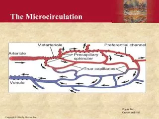
Microcirculation Lab. Thrombosis in the microcirculation. Bingmei M. Fu Department of Biomedical Engineering The City College of The City University of New York. Embolus. Thrombosis. Normal blood flow. 30 µ m. large vessel. microvessel. Thrombosis. Vessel injury. Surgery Trauma.

E N D
Microcirculation Lab Thrombosis in the microcirculation Bingmei M. Fu Department of Biomedical Engineering The City College of The City University of New York
Embolus Thrombosis Normal blood flow 30µm large vessel microvessel Thrombosis
Vessel injury Surgery Trauma Altered coagulability Flow Stasis Heart failure Prolonged immobilization Increased blood coagulability Thrombosis Risk Factors
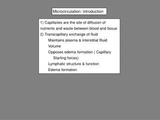
Thrombosis in microcirculation • Previous studies under conditions • flow retarded(Nicolaides et al., 1972); • flow disturbed • secondary flow in branches (Chen et al., 2004); • vessel injured/damaged by • electrical (Massad et al., 1987; Wong et al., 2000); • mechanical (oude Egbrink et al., 1988); • biochemical (Begent et al., 1970); • PDT, light/dye(Sato et al., 1990; Sasaki et al., 1996; Rucker et al.,2002).
Question 1 Can thrombosis occur in non-injured but bent/stretched microvessels under non-disturbed laminar flow (Re ~0.01) condition?
Question 2 What is the structural mechanism by which PDT induces thrombosis?
Experimental setup CCD camera
Experimental Design Sprague-Dawley rat, 250-300g; The mesentery gently arranged on the surface of a polished quartz pillar; With a microvessel (post-capillary venule, 20-50 µm) under observation, a rounded-tip glass restraining micropipette used to bend/stretch the microvessel.
micropipette inlet outlet Experimental Observations • In 10-60 min, thrombi formed in 19 out of 61 (~31%) sites in 28 non-injured bent/stretched microvessels; • all thrombi were initiated from the inner side of the curvature. (Liu et al, J. Biomech. 2008)
Results (Liu et al, J. Biomech. 2008)
What are the mechanical factors that initiate thrombosis in these non-injured bent/stretched microvessels?
Vessel Geometry θ A 90o B 2a A 2b 2r B A 180o B Ө microvessel diameter 2r = 25 µm (circular) equal perimeters of circular and elliptical cross sections (Liu et al, J. Biomech. 2008)
Numerical Methods • Fluent used to solve • Continuity Eq. • Navier-Stokes Eq. • Element No.: • 610x103, 770 x103 (90o/180o, circular); • 1.48x10⁶, 1.52 x10⁶ (90o/180o, elliptical); • µ = 2.5 cp (Levenson et al., 1990), ρ = 1050kg/m3; • Outlet pressure = 10 cmH2O, mean blood velocity = 1 mm/s, Reynolds No. ~ 0.01; • Convergence criteria: 10-8 of residues.
Velocity Distributions Circular Elliptical (Liu et al, J. Biomech. 2008)
Shear Rate Distributions A — A A A Circular max A A A A Elliptical A — A max A — A max (Liu et al, J. Biomech. 2008)
Shear Rate Distributions along the Curvature 90o 180o straight (Circular) (Liu et al, J. Biomech. 2008)
Shear Rate along the Curvature outlet inlet Circular outlet inlet Elliptical (Liu et al, J. Biomech. 2008)
Velocity along the Curvature inlet outlet Circular outlet inlet Elliptical (Liu et al, J. Biomech. 2008)
Circular Elliptical Pressure along the Curvature (Liu et al, J. Biomech. 2008)
Newtonian & non-Newtonian fluid Casson Model (Das et al., 1998, 2007) α= 1.621, β = 0.627 (Das et al., 1998); μp= 2.5 cP (Levenson et al., 1990). (Liu et al, J. Biomech. 2008)
Summary Thrombosis occurred in 19 out of 61 sites (31%) of 28 non-injured bent/stretched microvessels. Thrombi were initiated at the inner side of these microvessels. Numerical simulation results showed higher shear stress/rate and higher shear stress/rate gradient at the innersides of the bent/stretched microvessels, suggesting they were two mechanical factors that initiate thrombi.
Light-dye Treatment Light-dye treatment (Photodynamic Therapy, PDT): Use of a photosensitizer, activated by a laser of a specific wavelength, to treat tumor and other diseases in the presence of oxygen.
Advantages of PDT • Applied repeatedly at the same site; • Selective: photosensitizer can selectively accumulate in the tumor cells; • Harmless without light illumination; • Treatment for diseases that surgery is not possible (such as the upper bronchi, the structure cannot be removed surgically).
PDT Induced Thrombosis • Thrombi induced by light/dye consist primarily of platelets and occasionally of leukocytes in venules(Rumbaut et al., 2004). • The interaction between blood platelets and vessel wall plays an important role in thrombosis.
glycocalyx 150 nm Surface Glycocalyx (Squire et al., 2001)
Molecular Composition of SGL (Tarbell and Pahakis, J. Intern. Med , 2006)
Glycocalyx Layer Damage Light/dye increases the penetration of macromolecules in the endothelial surface glycocalyx of the vascular wall (Vink & Duling, 1996). Disruption of the glycocalyx would result in adhesion of platelets and blood cells to the vessel wall(Mulivor & Lipowsky, 2002).
Hypotheses PDT disrupts the endothelial surface glycocalyx increase microvessel permeabilityto water and solutes platelet and blood cells bindingto the endothelium and induces thrombi.
CCD camera Laser Spot Xenon Laser (495 nm) VCR Experimental Setup
Experimental Design • Sprague-Dawley rat, 250-300g; • Laser: Xenon laser, 495 nm, intensity 0.37 and 0.70 mW/mm2; • NaF: 50 mg/kg body wt., injected from the carotid artery; • With a microvessel (post-capillary venule, 20-50 µm) under observation, NaF was injected and the laser was turned on simultaneously.
20µm Thrombosis by Light/dye
15.5 ± 1.8 29.3 ± 2.2 2.5 3.8 Thrombus Growth Rate (Liu et al., BMMB, 2010)
Micropipette Marker Cell L0 2r dL/dt Blocker Technique of Lp Measurement (Curry, 1984)
30µm Lp Measurement
Lp Change under Light/Dye Treatment (Liu et al., BMMB, 2010)
* Early Change of Lp under Light/Dye Treatment (Liu et al., BMMB, 2010)
Results (Liu et al., BMMB, 2010)
Dye side Washout side 400 µm Measuring Window 200 µm 10 seconds (dI/dt)0 ∆Ifo Technique of P Measurement (Fu et al., 2005)
P to albumin * (Liu et al., BMMB, 2010)
* Early Change of P under Light/dye Treatment (Liu et al., BMMB, 2010)
Results (Liu et al., BMMB, 2010)
Lp P to albumin Baseline NaF + laser Baseline NaF + laser Comparison of Permeability Change w. & w/o. Blood Cells (Liu et al., BMMB, 2010)
What are the most likely structural mechanisms by which light-dye treatment induced microvascular hyperpermeability and thrombosis?
Model Geometry Y 2a Junction strand Δ Surface glycocalyx Lumen side Tissue side Tissue side 2D X O 2d Lumen side Lf L Z X Y 2B 2d L 2D Lf (revised from Fu et al., 1994)
Model Predictions (Liu et al., BMMB, 2010)
0.14 Model Predictions and Exp. Results
Summary Light/dye treatment with 0.37mW/mm2 induced thrombosis in 3.8 min, complete occlusion at ~29 min. This power gradually increased Lp and Palbumin to a plateau in 3 – 5 min by 2.2-fold and 4.1-fold respectively. Our model predictions indicated that Lp and P increase under light/dye treatment was most likely due to 86% - 92% diminishmentof the endothelial surface glycocalyx.