Download
1 / 33
330 likes | 441 Views
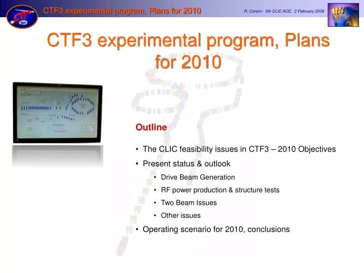
CTF3 experimental program, Plans for 2010. Outline The CLIC feasibility issues in CTF3 – 2010 Objectives Present status & outlook Drive Beam Generation RF power production & structure tests Two Beam Issues Other issues Operating scenario for 2010, conclusions.

E N D
CTF3 experimental program, Plans for 2010 • Outline • The CLIC feasibility issues in CTF3 – 2010 Objectives • Present status & outlook • Drive Beam Generation • RF power production & structure tests • Two Beam Issues • Other issues • Operating scenario for 2010, conclusions
CTF3 2010 main goals (feasibility demonstration) • Drive Beam Generation • Bunch train recombination 2 x 4 in DL and CR (from 3.5 to 28 A) • Transverse rmsemittance < 150 p mm mrad (combined beam) • Bunch length control to < 1 mm rms (combined beam) • Beam current stability ~ 0.1 % for combined beam • RF Power Production • 20.8 A beam-powered test of a single PETS (without re-circulation) in the TBTS • 135 MW (with 28 A potentially available in CLEX, the peak power can reach 240 MW) • 140 ns total pulse length • A measured breakdown rate in the range of 10-4 or lower • Operation of a few hundred hours at 1 Hz • 7.4(10) A beam-powered test of a single PETS with external recirculation in TBTS • 135 (81) MW circulating power or 65 (65) MW available for accelerating testing • 250 ns total pulse length, 100 (170) ns flattish-top • A measured breakdown rate in the range of 10-4 or lower • Operation of a few hundred hours at 5 Hz • On/off/adjust will be demonstrated using the external reflection/recirculation system mounted on one of the PETS in TBL. • Two Beam Acceleration issues • TBTS • Improved measurements of power and energy loss. • Breakdown transverse kick measurements. • Probe Beam energy gain and beam loading tests. • TBL • The current schedule is to have 8 PETS installed as well as a spectrometer dump for energy spectrum studies, toward the summer 2010. This will allow to verify transport of a beam with up to 30% of the energy extracted.
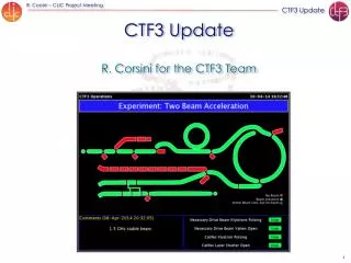
2009 CTF3 experimental program Goals • 30 GHz: One structure test (TM02) + breakdown studies • PHIN Beam characterization, reach ½ of nominal bunch charge ? • CALIFES Beam characterization, beam to TBTS (most likely still reduced current) • Delay Loop Back in operation, retrieve combination x 2 (~ 7 A) • Combiner Ring Final optics checks, isochronicity, put together with DL (> 24 A) • TL2 Complete commissioning (tail clipper), bunch length control, > 20 A to users • TBTS PETS to nominal power/pulse length (15 A, recirculation) • Beam commissioning of probe beam line • First accelerating structure tests (one structure ? – CLIC G) • Two-beam studies (deceleration/acceleration), initial breakdown kicks studies • TBL PETS validation (100 MW, need > 20 A), beam line studies (2-3 PETS ?) • OthersCDR studies in CRM, beam dynamics benchmarking, stability studies, control of beam losses… Nominal reached ~ 28 A Max ~12 A 170 MW, 200 ns No structure available ~20 MW with 10 A Only one PETS installed
Drive Beam Generation • Bunch train recombination 2 x 4 in DL and CR (from 3.5 to 28 A) • Transverse rmsemittance < 150 p mm mrad (combined beam) • Bunch length control to < 1 mm rms (combined beam) • Beam current stability ~ 0.1 % for combined beam • Quite close to all requirements already at the end of 2009
CTF3 – Layout DELAY LOOP COMBINERRING DRIVE BEAM LINAC CLEX CLIC Experimental Area
CTF3 – Current Up to 7 A Up to 5 A – 1.2 ms 120 Mev 28 A – 140 ns 120 Mev Up to 7 A
CTF3 – Emittance & bunch length < 100 p mm mrad ~ 70 p mm mrad ~ 1 mm rms < 150 p mm mrad, combined, vertical < 50 p mm mrad ~ 1 mm rms < 1-2 mm rms from 12 GHz power measurements
Delay loop & combiner ring: THE recombination ONLY DL DL & CR ONLY CR
TL2, TL2’, TBTS beamlines • Line optics looks about OK (kick measurements), but difficult matching • Non-combined beam transported to TBTS and through PETS with small losses (about 10%) • Combined beam (factor 4) transported to TBTS with losses, from 15 A from ring to about 12 A - no local losses in PETS 21 Aug 21 Aug
Drive Beam Generation – 2010 outlook • Bunch train recombination • Consolidate results, routine operation, stability of fully combined beam • Transverse rmsemittance • Complete TL2, TL2’, TBTS commissioning – full transport to CLEX • < 100 p mm mradafter ring, combined beam • < 150 p mm mradin CLEX, combined beam • Bunch length control to < 1 mm rms(combined beam) • Measurement campaign with different meas. systems (RF defl.& screen, fast streak-camera, RF monitors) • R56 tuning experiments in Frascati chicane and TL2 • Beam current stability : improve slow variations, obtain ~ 0.1 % for combined beam • Full measurement campaign (find correlations, jitter sources) • Gun pulse flatness, “slow” feedback • Improve overall klystron stability (at least up to best performing klystrons) • Slow RF feedback (temp. in pulse compressors)
f k PETS TBTS, PETS conditioning • Max beam current through PETS ~ 12 A • Aggressive, fast conditioning - well beyond CLIC nominal power • Pulse shortening in splitter and phase shifter variablesplitter variablephase shifter Prediction Measurement
TBTS, PETS conditioning Variable RF power splitter Variable RF phase shifter Max power reached 170 MW (peak) Total pulse length about 200 ns – no flat top 3 July 135MW for CLIC
PETS on/off Reflection=0 dB ON Power attenuation vs. piston position (full reflection in OFF position) -1 dB Stroke 7.7 mm -3 dB -6dB OFF, full PETS coupler design with integrated RF reflector Stroke 7.7 mm ON PETS output (steady state) 0.26 ON Structure input OFF OFF, full
PETS on/off • Remarks: • High power tests of components and concept validation (slow movement, external reflector) will be done in 2010 in the TBTS PETS. • Meanwhile, the 25% power reduction can be tested this spring at SLAC with the new PETS (under construction). • The fast (~ 10-15 ms), vacuum compatible linear actuator prototype should be ready for testing in TBTS by mid 2010.
RF Power Generation – 2010 outlook • PETS TBTS • Initial configuration with variable power splitter & phase shifter • Fast fall-back solution: recirculation with no active elements (maximum power to accelerating structure) • Goal: nominal power /pulse length inside PETS - with recirculation (135 MW, 250 ns total pulse length, 170 ns flat-top) • Breakdown rate measurements (at high BD rate - extrapolation to lower rates) • Operation w/out recirculation (end of the year?) – may have different breakdown rate… • Test of new PETS on-off scheme (components and concept) • Acc. structure in TBTS • TD24, initial conditioning in the shadow of PETS operation • Goal: nominal power / pulse length delivered to structure (65 MW, 250 ns total pulse length, 170 ns flat-top) 12 GHz TD24. structure under assembly before installation in TBTS
CALIFES • CALIFES beam in the final spectrometer • Full transport through TBTS (no aperture restriction yet) • Reached 140 MeV, 0.6 nC/bunch, total > 7 nC for 20 ns • Beam emittance optimization under way • (last measurements ~ 20 p mm mrad) Specifications Energy ~ 200 MeV Emittance< 20 .mm.mrad Charge per bunch : 0.6 nC Energy spread <2% Number of bunches : 1 to 226 Bunch length (rms) : 0.75ps Bunch spacing : 667ps
TBL • A few tests done in the (short) TBL • Up to 10 A, about 20 MW power produced (240 ns) • Good agreement with expectations • Sensitive to bunch length – in best conditions form factor equal to one, within measurement precision
TBL • Full line installed • Up to 8 PETS should be installed before the end of the year
Two Beam Issues – 2010 outlook • TBTS • Two-Beam test – consistency between power & beam energy gain, 100MV/m • Drive beam, deceleration, power produced • Probe beam, power delivered to accelerating structure, energy gain • Beam Loading compensation experiment - by variable fast phase switch – check control of RF pulse shape with probe beam acceleration • Measurement of breakdown kicks • Measurement of effect of beam loading on breakdown rate • TBL • Complementary measurement of deceleration / produced power. • Goal: deceleration by 30% (need 8 PETS installed). Measurement of energy spectrum. • Optics, steering algorithm studies.
Other Issues – 2010 outlook • CALIFES • Fully reach nominal parameters (total charge) • Bunch length measurements (RF defl. & screen) • PHIN • Two runs planned • Run 1: complete measurement program • Run 2: test of phase coding • Other • First measurements of phase stability (PETS output, RF pickups…) • Operation at 5 Hz (or more) • Control of beam losses • Coherent Diffraction Radiation (RHUL collaboration) • …
Operating scenario for 2010 (an exercise) Optics improvements (DL dispersion) Full transport to CLEX Bunch length control (first tests) PETS conditioned to nominal power/pulse length Accelerating structure conditioned to nominal power/pulse length • Two-Beam test • power & energy gain, • 100MV/m • 1st TBL PETS installation PETS breakdown rate measurements? • TBL studies • Beam Loading compensation experiment • Measurement of breakdown kicks • 2nd run PHIN • Measurement of effect of beam loading on breakdown rate Test of new PETS on-off scheme • TBL studies 30% deceleration • Stability studies & improvements • PETS no recirculation • Phase stability • Operation at 5 Hz (or more) • Control of beam losses • Coherent Diffraction Radiation … • 2nd TBL PETS installation
CTF3 2010 outlook • Drive Beam Generation • Bunch train recombination 2 x 4 in DL and CR (from 3.5 to 28 A) • Transverse rmsemittance < 150 p mm mrad (combined beam) • Bunch length control to < 1 mm rms (combined beam) • Beam current stability ~ 0.1 % for combined beam • Drive Beam Power Production & Two Beam Acceleration • 20.8 A beam-powered test of a single PETS (without recirculation) in the TBTS • 135 MW (with 28 A potentially available in CLEX, the peak power can reach 240 MW) • 140 ns total pulse length • A measured breakdown rate in the range of 10-4 or lower • Operation of a few hundred hours at 1 Hz • 7.4(10) A beam-powered test of a single PETS with ext. recirculation in TBTS • 135 (81) MW circulating power or 65 (65) MW available for accelerating testing • 250 ns total pulse length, 100 (170) ns flattish-top • A measured breakdown rate in the range of 10-4 or lower • Operation of a few hundred hours at 5 Hz • On/off/adjust will be demonstrated using the external reflection/recirculation system mounted on one of the PETS in TBL. • TBTS • Improved measurements of power and energy loss. • Breakdown transverse kick measurements. • Probe Beam energy gain and beam loading tests. • TBL • The current schedule is to have 8 PETS installed as well as a spectrometer dump for energy spectrum studies, toward the summer 2010. This will allow to verify transport of a beam with up to 30% of the energy extracted. Will be OK, possibly somewhat reduced performance… Overall reasonable goals, but difficult to have a few hundred hours, and 5 Hz TBTS studies and especially TBL results can happen only quite late in 2010…
Variable phase shifter Variable power splitter Prediction Measurement
PHIN status • First run in 2009 very successfull • Bunch charge up to 2.5 nC, above nominal • Beam energy ~ 5-6 MeV • Emittance measured ~ 7 p mm mrad • Very good agreement with simulations • Several potential improvements identified, will be implemented for next run • Aims for next run: stability (short and long term)