Download
1 / 13
130 likes | 217 Views
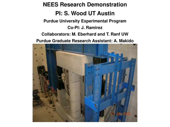
NEES Research Demonstration PI: S. Wood UT Austin Purdue University Experimental Program Co-PI: J. Ramirez Collaborators: M. Eberhard and T. Ranf UW Purdue Graduate Research Assistant: A. Makido. Purdue Experimental Program. f’ c = 5000 psi

E N D
NEES Research DemonstrationPI: S. Wood UT AustinPurdue University Experimental ProgramCo-PI: J. RamirezCollaborators: M. Eberhard and T. Ranf UWPurdue Graduate Research Assistant: A. Makido
Purdue Experimental Program f’c = 5000 psi N = 0.08f’cAg (180 kips for Specimen 2 and 45 kips for Specimen 1)
Specimen 1- Bent Column Ag= 113 in2 ρg= 1.6 % ρs= 0.9 % (Specimen 1-1) = 0.6 % (Specimen 1-2) 16-#3 Bars 0.75 in. Cover ρg : reinforcement ratio ρs : volume ratio of spiral hoop to the core volume Spirals W2.9@ 1.25 in. (Specimen 1-1) W2.9@ 2.25 in. (Specimen 1-2) 12 in.
Specimen 2- Single Column Ag= 452 in2 ρg= 1.6 % ρs= 0.9 % (Specimen 2-1,2-2) = 0.6 % (Specimen 2-3) 16-#6 Bars 1.5 in. Cover ρg : reinforcement ratio ρs : volume ratio of spiral hoop to the core volume Spirals #3@2.5 in. (Specimen 2-1 and 2-2) #3@3.5 in. (Specimen 2-3) 24 in.
Loading direction Column Cross Section Longitudinal strain gage Transverse strain gage 6” 6” 3” 3” 2.5” d/2=12” d=24” 120” d=24” d/2=12” 2.5” Strain gage Instrumentation Plan
Loading direction Column Cross Section Potentiometer Steel Angle Bar 2.5” d/2=12” d=24” Potentiometer Instrumentation Plan 120” d=24” d/2=12” 2.5”
Construction of Specimen 1-1 Spiral Hoop with Instrumentation Casting of column
Construction of Specimen 2-1 Assembling Spiral Hoop Casting of column
Proposed Displacement History : Test Stage at Reno 16 8Δ’y 15 6.4Δ’y 4.8Δ’y 14 13 3.2Δ’y Pre-yielding 1.6Δ’y 1Δ’y Pre-cracking Δ’y: average measured displacement corresponding to longitudinal reinforcement strain gauges first yield