Download
1 / 33
330 likes | 522 Views
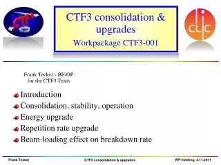
CTF3 lasers. Marta Csatari Divall Eric Chevallay, Valentine Fedosseev, Nathalie Lebas, Roberto Losito, Massimo Petrarca, CERN, EN-STI. Outline. Photo-injectors for CTF3 Current laser setup Results on PHIN Feedback stabilization Phase coding Laser for CLIC Future plans.

E N D
CTF3 lasers Marta Csatari Divall Eric Chevallay, Valentine Fedosseev, Nathalie Lebas, Roberto Losito, Massimo Petrarca, CERN, EN-STI
Outline • Photo-injectors for CTF3 • Current laser setup • Results on PHIN • Feedback stabilization • Phase coding • Laser for CLIC • Future plans
Photo-injectors for CTF3 Combiner Ring: x4 Delay Loop:2 Drive Beam Injector thermionic gun Possible change over in next few years Drive Beam Accelerator PHIN http://clic-study.web.cern.ch/clic-study/ PHIN Drive beam photo-injector test stand CLEX 2 beams test area CALIFES Probe beam photo-injector Machine parameters set the requirement for the laser UV laser beam
Laser requirements Achieved Not available yet Feed-back stab. Phase-coding test The laser was not designed for CALIFES parameters 3.6kW 4.67mJ in 1.2μs 1.25kW 1.5mJ in 1.2μs 1.5 GHz Synched oscillator Cw pre-amplifier 10W 3-pass amplifier 3.5kW 2-pass amplifier 8.3kW 7.8kW 14.8mJ in 1.2μs 2ω 4ω Feed-back stab.
Outline • Photo-injectors for CTF3 • Current laser setup • Results on PHIN • Feedback stabilization • Phase coding • Laser for CLIC • Future plans
Contributions Harmonics Phase-coding test Phase-coding test Cooling 3.6kW 4.67mJ in 1.2μs 1.25kW 1.5mJ in 1.2μs 1.5 GHz Synched oscillator Cw pre-amplifier 10W 3-pass amplifier 3.5kW 2-pass amplifier 8.3kW 7.8kW 14.8mJ in 1.2μs 2ω 4ω AMP1 head assembly HighQ front end AMP1 and AMP2
Amplifiers NEW!
Harmonic stages Preliminary measurement on response to long train 1.2 μs Amp2 as in table • 1 cm KDP • 18% efficiency • Flat response • Beam size/ shape to be • optimized Amp1 only X4 less intensity
Outline • Photo-injectors for CTF3 • Current laser setup • Phase coding • Diagnostics/Results on PHIN • Feedback stabilization • Laser for CLIC
Laser diagnostics CALIFES PHIN ~70m 64% to cathode under vacuum Beam transport ~11m 71% to cathode 2δ beam radius (mm) • Transmission is low for CALIFES line • Pointing instabilities are high due to long distances • Closer to the gun would be better • Automated measurement system needed Distance from 4th harmonic crystal (mm)
Current status on PHIN pointing Taken with virtual cathode camera and OTR screen camera
Current status on PHIN amplitude In laser room In PHIN Thanks to PHIN team • Exceptional stability without feedback stabilization! • Pointing instabilities can be improved by better airflow control • Amplitude feedback system is necessary Current: sigma =0.8 %
Outline • Photo-injectors for CTF3 • Current laser setup • Results on PHIN • Feedback stabilization • Phase coding • Laser for CLIC • Future plans
Sources of instabilities • Some also affecting the measurement system!
Sources of instabilities Mirror inside the gun • Improving the environment • for the laser is necessary: • Better temperature stabilization • Less airflow, better enclosure (planned for May 2010) • Move the laser closer to the gun • Change to solid metal mirror
Scheme to improve stability • Similar system tested at RAL with 4 μs speed →0.25%RMS over 140 μs in the UV • Commercial LASS-II by Conoptics at green wavelength • 1/1@ 500kHz (Int. Ref. Mode) • 5/1 @ 100kHz • 18/1 @50kHz • 100/1 @10kHz • 200/1 @1kHz • 250/1 @200hz • Custom design for quasi-cwavailable • EO modulators ordered for in house tests • System specifications by spring 2011 Noise measured on PILOT system Could be reversed for feed forward option In TESLA this system was invented by I. Will and his group 0.7% rms stability was achieved from 3% with 70% transmission HOW to measure? • Development of a measurement system with >104 dynamic range is necessary • Challenging task with the phase-coded short train • More detailed fast noise measurements planned for 2010
Outline • Photo-injectors for CTF3 • Current laser setup • Results on PHIN • Feedback stabilization • Phase coding • Laser for CLIC • Future plans
Phase-coding • Slow switching demonstrated • Recombination and delay measured • Damage due to the high input power, only 10mW output • RF driver is not up to our specification(see picture) Driver response to square input (voltage applied to modulator) Losses in % 82% 20% waveplate 20% EO modulator 333ps delay T=9% Oscillator 320mW 11% Fiber outcoupler EO modulator Variable attenuator 11% 2% splitter Fiber coupler 20% NEW scheme 82% • Components in purchasing • Booster amplifier ordered in Feb/2010 • Planned commissioning on PHIN autumn/2010 Booster amplifier 300mW Losses in % waveplate 2% 2% 2% 55% 2% Full power train from amplifiers 5% Polarizer Polarizer waveplate T=38% Pockels cell Alternative scheme Polarizer 2% • Driver specification is very demanding (3.6MHz, fast rise time ,high average power) • Monitor latest status for available drivers on the market Lens system With type2 crystal we could get T=80%
Outline • Photo-injectors for CTF3 • Current laser setup • Results on PHIN • Phase coding • Feedback stabilization • Lasers for CLIC • Future plans
Main challenges identified • Lack of laser time for research development on the laser • Long train operation for CLIC (140 μs) • High average power operation (100Hz) • Stability and stabilization • (Phase coding on the way independently from operation until installation on PHIN ~October 2010)
Modifications to the setup • Using ‘leakage’ wherever we can • No interruption to operation • High repetition rate test are risky and still cannot be performed
Independent laser system for CALIFES • Laser design was for long trains of the CLIC drive beam • CALIFES requires only up to 226 pulses (160ns) • 1μJ in the UV is necessary for short train, which have not been delivered yet • CALIFES will be used as a diagnostic test bench until 2015 at least PILOT laser tested on CTF2 This is how long the CALIFES train is Allow the amplifier to store the energy before pulses arrive Higher energy can be reached Stability needs to be investigated • ~60kEuro for replacing old parts • The footprint is 60cm X 150 cm + the oscillator • Deliverable by Spring 2011 • In collaboration with IAP for amplification • Rest of the system needs new oscillator For <1% change at the output the switch on time has to be <350ns accurate <1% variation over the train at nominal energy
New source for PHIN laser and CLIC • 500MHz front end andthe existing amplifiers could be used for tests for CLIC • With reprate tripling configuration PHIN could still be used as it is • High repetition rate operation/fracture/thermal lensingto be studied • Non steady-state operation and pre-pumping to be tested • It would also be a useful source for cathode studies • Commercial oscillator+ pre-amplifier+ harmonic stages is available (up to 30W in the IR ~15W in green without amplification) • ~200kEuro • 4 months from order • 3 months for tender • After proof of new configuration for CALIFES laser
Feasibility for CLIC laser Current amplifiers in a pre-pumped mode with a pre-shaped pulse Steady state operation with an additional amplifier After 1st amplifier After 2nd amplifier Pre-shaped input pulse By Mikhail Martyanov from IAP • ~20kEuro • 3-4 months development for driver electronics • 5 weeks testing • In collaboration with IAP • Stability can be an issue • We are working well above saturation fluence • We are close to fracture limit • Slab amplifier might be better solution • Further feasibility is required in 2010/2011 • 1 year for tender for diodes/drivers and chiller • With original design 600kEuro • STFC doing feasibility for SLAB geometry
Future plans • 2010 • Detailed noise measurements (laser and PHIN) • Improved laser environment by autumn • Implementation and test of phase-coding • 2011 • Implementation and test of feedback • stabilization system • Noise measurements on the machine • Long train harmonics stages • Design studies for CLIC laser
Harmonic stages Mikhail Martyanov, GrigoryLuchinin, Vladimir Lozhkarev IAP 50% conversion efficiency 40% conversion efficiency G. CHEYMOL- M. GILBERT CEA Pulse Picker bypass for PHIN
Noise response Effect of 100 kHz seed modulation on the output (PILOT laser 2004 ) • Response time of the amplifier will depend on the gain and the relaxation time and output fluence • Fast input variations will not be damped
Steady-state MOPA Pumping diodes Current overshoot <1% Ripples <1% Temperature How is the output power affected by the input parameters? Interlinked with all the others Oscillator and preamp from HighQ < 0.2 % rms above the 100 kHz noise region <1% rms below the 100kHz noise region • The best technology for the time was bought • We are more sensitive to pump variation • Stabilized diode technology should be investigated • 0.33% RMS stability is measured in the IR
Long train test bench • Using the rejected beam after 1stPockels-cell • This would allow us to do independent tests during CALIFES operation • Long train studies on the harmonic stages should be done with existing amplifiers • Feedback stabilization and stability measurements could be carried out at different wavelengths ~30kEuro for hardware 2-3 months for stability measurements (starting summer 2010) Specification of feedback stabilization system (by end of 2010) 4-6 weeks harmonics studies and fracture limit test (September 2010) 2-3 months crystal temperature stabilizer development 2 months feedback stabilization with new electronics (by spring 2011) Starting summer 2010