Download
1 / 35
2.17k likes | 5.22k Views
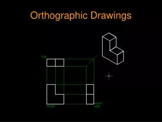
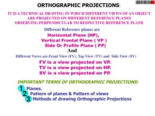
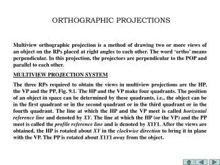
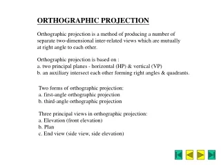
Orthographic Drawing. Orthographic Projection. An orthographic projection is a 2 dimensional representation of a 3 dimensional object. Six Principle Views. Any object can be viewed from six perpendicular views. The Glass Box.

E N D
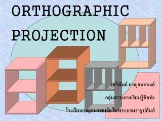
Orthographic Projection • An orthographic projection is a 2 dimensional representation of a 3 dimensional object.
Six Principle Views • Any object can be viewed from six perpendicular views
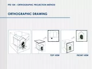
The Glass Box • One way to understand the standard arrangement of views on a sheet of paper is to envision the object in a glass box • The outside observer would see six standard views of the object through the sides of this imaginary glass box
Glass Box Method • Glass Box Method: • The object is placed in a glass box. • The image of the object is projected on the sides of the box. • The box is unfolded. • The sides of the box are the principle views.
Glass Box Method • The object is placed in a glass box. • The side of the box represent the 6 principle planes.
Create the orthographic projections for the following object. The height and depth of is equal to 3 grid squares.
Create the orthographic projections for the following object.
Number of Required Views • When drawing an orthographic projection you must include the appropriate number of views to fully describe the true shape of the part. • You may use a fewer number of views if you can fully describe the part in the given views. • How many views are required to fully describe a rectangular box? • How many views are required to fully describe a sphere?
Number of Required Views • You may use additional views, such as the left, back, or bottom views to describe an object if the object cannot be fully described in the three standard views. • additional views such as section views, detail views and auxiliary views may also be drawn to fi.
Measurement Transfer Between Views • Top and Bottom views show LENGTH and WIDTH. • Left and Right views show HEIGHT and WIDTH • Front and Rear views show HEIGHT and LENGTH. • The line (drawn at a 45° angle) is used to transfer depth measurements between the top and right side (or left side) views.
Normal Plane • Normal Planes will appear as an edge in two views and a true sized plan in the remaining view when using three views such as a top, front and right side.
Inclined Plane • Inclined Planes will appear as an edge view in only one of the three views. • The inclined plane will appear as a rectangular surface in the other two views.
Oblique Planes • Oblique Planes will not appear as an edge view in any of the six views since they are not parallel or perpendicular to the projection planes. • They always appear as a “plane” and have the same number of corners in each of the six views.
Foreshortened Lines Identify the foreshortened lines in the orthographic projection below.
Curved Surfaces • A cylinder will appear as a circle in one view and a rectangular shape the other two views.
Axis and Center Lines • The axis appears where the cylinder appears rectangular. • Center marks are used to identify the center of the cylinder where it appears circular.
Choosing the Front View • Considerations when choosing the front view of an object. • Chose the view that shows the most features or characteristics of the object • Choose the view that contains the least number of hidden lines. • Choose the view so the part is oriented with its longest length parallel to the bottom of the drawing.
First- and Third-Angle Projection • There are two main systems used for projecting and unfolding the views: • Third-angle projection which is used in the United States, Canada and some other countries • First-angle projection which is primarily used in Europe and Asia • You should understand both methods
Hidden Lines • An advantage of orthographic views is that each view shows the object all the way through as if it were transparent • Thick dark lines represent visible features • Dashed lines represent features that would be hidden behind other surfaces • When possible, choose views that show features with visible lines
Centerlines • The centerline is used to: • Show the axis of symmetry of a feature or part • Indicate a path of motion • Show the location for bolt circles or other circular patterns • The centerline pattern is composed of three dashes, one long dash on each end with a short dash in the middle
Precedence of Lines • When lines coincide on a drawing the rules of precedence are: • Visible lines always take precedence over hidden or centerlines • Hidden lines take precedence over centerlines
Drawing Pencils • ENGR 123 Drawing Conventions • Section Lines = 0.5 mm HB • Visible Lines = 0.7 mm HB • Hidden Lines = 0.5 mm HB • Centerlines = 0.5mm HB • Construction Lines = 0.5mm 2H
Lines Types andOrder of Precedence 1 0.7 mm 2 0.5 mm 0.5 mm 3
Planning Your Drawing or Sketch • When laying out a drawing sheet you will need to consider: • Size and scale of the object • Sheet size • Measurement system • Space necessary for notes and title block
Putting it all together… • Choose the front view. • Determine the number of required views. • Identify the scale. • Draw visible lines for the front view. • Project the feature to draw the top view. • Draw the hidden lines. • Draw the center lines and center marks.
Draw the orthographic projections needed to fully describe the part. Choose the best view for the front view. Use a scale of 1:1 with 2” spacing between the views