Download
1 / 27
270 likes | 271 Views
ALICE Trigger Upgrade CTP and LTU Design Review. Summary of current Trigger System and Introduction to Trigger Upgrade,. David Evans. ALICE CTP and LTU Upgrade Design Review CERN 27 th January 2016. This Morning’s Presentations.

E N D
ALICE Trigger Upgrade CTP and LTU Design Review Summary of current Trigger System and Introduction to Trigger Upgrade, David Evans ALICE CTP and LTU Upgrade Design Review CERN 27th January 2016
This Morning’s Presentations Summary of Current System and Introduction to Upgrade. David Evans System architecture and protocols Roman Lietava Hardware Marian Krivda Software Anton Jusko Budget, schedule, resources David Evans Integration, production, system tests Roman Lietava
Layout of First Talk • Overview of the Central Trigger Processor (CTP) • Trigger classes • Sub-detector clusters • Past-future protection • The Local Trigger Unit • Emulation of the CTP • Error generation • Upgrade for Run2 • The LM0 Board • Trigger Requirements for Run 3
Highlights of the ALICE CTP Upgrades in Run 1: • L0 can be transmitted over TTC (as well as LVDS cable). • Status of trigger inputs transmitted to DAQ at time of L0 trigger. • Functionality of TTCvi board incorporated in LTU • Three levels of hierarchical hardware triggers: • L0 (1.2µs after beam interaction) → L1 (6.5µs) → L2 (88 µs) • At any time, 24 ALICE sub-detectors dynamically partitioned in up to 6 clusters. • Cluster configuration arbitrary and fully programmable – could be exclusive, • more likely to overlap. • Past-future Protection logic selects events with either no pile-up, or • a number of pile-up interactions up to a programmable limit. • Independent protection for each cluster; operates on all three trigger levels. • (Not used much in Run 1) • Data traffic over the TTC system • Channel A: L1 signal • Channel B: Orbit, Pre-pulse • But also, for each trigger: • L1 Data Message - 5 16-bit words • RoI Message - 4 words (never used) • L2a Message - 8 words
Position of CTP crate in ALICE • Racks are located below the Di-Muon magnet in cavern. • short latency for L0 – 1.2µs, but… • stray magnetic field • low-level radiation • no access when beam is on • TTC crate supplies LHC clock direct to CTP and to Time-of-Flight detectors. • CTP sends L0, L1, L2 signals and messages to sub-detectors via individual TTC partitions.
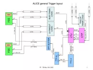
Context diagram of the Central Trigger Processor (CTP) CTP inputs • LHC timing – BC, Orbit • 60 trigger inputs 24 L0 24 L1 12 L2 • 24 BUSY inputs CTP outputs • 24 independent sets 7 outputs per sub-detector CTP readout Trigger data for events accepted at L2 level Interaction Record CTP interface ECS, DAQ, RoIP (never used)
Block diagram of the CTP • Synchronous, pipelined processor • 40.08 MHz bunch-crossing clock (BC) Modularity and scalability Logic blocks designed as individual VME boards • 6U form-factor • 8 PCB layers • moderate density
CTP boards in a VME crate Front panel connections • Timing inputs • Trigger inputs • BUSY inputs • CTP outputs • Interface links Internal connections Custom backplane
Trigger (Physics) Classes Trigger class - a basic processing structure throughout the CTP logic • There are 50 independently programmable “physics” classes • An additional test class - software-triggered, configured “on the fly” (application: calibration trigger, etc.) “Rules of engagement”: • A cluster can be associated with an arbitrary number of trigger classes • A trigger class, on the other hand, affects only a single cluster • The associations are programmable
Generation of the Class L0 Trigger • Trigger input selection: • fully programmable • Shared resources: • 2 Scaled-down BCs (1 – 109) • 2 Random triggers (1 – 109) • 4 BC Masks (1 bit per bunch) • Reduction of the class-trigger rate • trigger pre-scalers (1 – 106) • Cluster selection: • Cluster BUSY (1 out of 6) • Mandatory global vetoes: • DAQ BUSY (trigger enable) • CTP BUSY (CTP readout) • CTP Dead Time (1.5µs)* • All/Rare: • boosts the acquisition of rare events * Practically has no effect on trigger efficiency
Past-future Protection circuit • 4 independently programmable circuits at each trigger level (+1 for Test Class) • 2 identical blocks, based on dual-port memory • Sliding time-window during which the interaction signal (INTa/b) is counted • Programmable parameters: • Protection interval (ΔTa/b) • 2 Thresholds (THa1/2, THb1/2) • Output delay (a/b) • Output logic function • Delay and alignment of output signals
Local Trigger Unit (LTU) • Uniform interface between the CTP and sub-detectors: • easier control • easier mods/upgrades • Unique features: • Full CTP emulation (stand-alone mode) • Error emulation (front-end tests) • VME, 6U form-factor • Similar to other CTP boards
Context diagram of the LTU • Front panel connections: • Inputs from CTP (LVDS) • Outputs to TTCvi, TTCex • L0, BUSY – sub-detector • TTCvi functionality now incorporated in upgraded LTU firmware (LTUvi) • Hence no longer used.
Block diagram of the LTU LTU modes: • Global (run) mode - propagates CTP signals • Stand-alone mode - provides full CTP emulation
CTP designed to handle up to 24 simultaneous L0 inputs covered all known L0 inputs plus gave 6 spare at time of construction. Switchboard • Explosion of possible L0 inputs in last 2 years 18 >40 (although not all needed in single run) • Solution: make Switchboard from programmable fan-in/out boards. • 24 L0 inputs can be chosen from 50 at any time. • All 50 switchboard inputs can be monitored – even if not included in trigger.
Requirements for CTP for LHC Run 2 Add LM trigger level (before L0 trigger level) for TRD pre-trigger Increase number of classes from 50 to 100 Trigger input switch integrated into CTP New snapshot/generator memory (using 1+1 GB of DDR3 memory) All functions (special type of trigger inputs) from 8 inputs (only 4 inputs before) LM and L0 interactions (definition of basic trigger) from first 8 inputs Past-Future protection for LM and L0 levels (protects detectors from Pile-Up) Second link to DAQ for extended Interaction record (DDL2 firmware implemented in CTP LM0 FPGA)
ALICE CTP for LHC Run 2 Changes with respect to LHC Run 1 • New LM0 board with Kintex-7 FPGA • 96 diff. IOs at front panel • New octopus cable (blue) for CTP inputs • New Detector Data Link (DDL2) to DAQ • New FPGA for LM0, all other CTP and LTU boards, updated • Installed new trigger cables from T0, V0, CPV and DCAL • Repaired many old cables • Timing on CTP backplane, CTP-LTU and LTU-TTCex connections re-checked after upgrade of all FPGA designs
LM0 board BC input (ECL) ORBIT input (ECL) 2 GB DDR3 memory • SAMTEC FireFly cable • 12 diff. links • SFP+ • link to DAQ Kintex-7 FPGA • 96 LVDS I/O • Trigger inputs • BUSY inputs • LM output Power controllers New LM0 board designed as a CTP prototype for Run 3
Summary of Upgrades Muon Forward Tracker (MFT) MAPS Inner Tracking System (ITS) Muon Arm Readout Trigger electronics (CTP + LTUs) Data Acquisition (DAQ) High Level Trigger (HLT)
CTP Requirements for Run 3 • Interaction Rates: 50 kHz for Pb-Pb, and up to 200 kHz for p-p and p-Pb • 2 modes of running for detectors: triggered and continuous • The main “interaction” trigger via the “FIT” detector • 3 different latencies (LM, L0, L1) • Triggers sent to all detectors which are not busy, but retain also clustering possibility • For detectors using the CRUs, BUSY is really a throttle as large latency means trigger will continue to be sent after BUSY is set. • No CTP Dead-time • 3 types of trigger data distribution • Directly on detector (ITS and MFT detectors) • Via Common Readout Unit (CRU) • Via detector specific readout system
Requirements for LHC Run 3 (cont.) • 2 types of link layer (both optical) • GBT (PON) for upgraded detectors • TTC system for old detectors • 14 detectors (9 with GBT system, 4 with TTC system, TRD (TTC+CRU)) • 6 Triggering detectors (FIT, ACO, EMC, PHO, TOF, ZDC; 22 inputs ) • Trigger Input latencies (time from interaction to signal at detector CTP input) • 425 ns (contributing detector – FIT) Interaction (Minimum Bias) trigger • 1.2 µs (contributing det. – ACO, EMC, PHO, TOF, ZDC) • 6.1 µs (EMC, ZDC) • Note each detector sees only ONE trigger (LM, L0 or L1
Concept for New Trigger System • Keep the notion of the CTP • But advances in technology mean we can have CTP on a single 6U Board • Keep the notion of LTU • As the interface between CTP and detector/CRU • And as a standalone CTP emulator
Summary • Current Trigger system has worked well for ALICE • New LM0 board has worked well in the ALICE environment during 2015 • LM0 Board serves as the CTP prototype for Run 3 • and LTU pre-prototype • For Run 3 we proposed to have a CTP on a single board • And keep the LTU concept • The new trigger electronics will also be backward compatible with detectors not upgrading