Download
1 / 16
160 likes | 284 Views
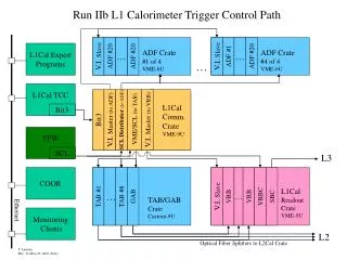
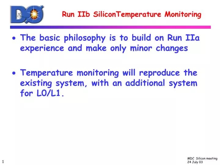
Run IIb SiliconTemperature Monitoring. The basic philosophy is to build on Run IIa experience and make only minor changes Temperature monitoring will reproduce the existing system, with an additional system for L0/L1. Temperature Monitoring.

E N D
Run IIb SiliconTemperature Monitoring • The basic philosophy is to build on Run IIa experience and make only minor changes • Temperature monitoring will reproduce the existing system, with an additional system for L0/L1.
Temperature Monitoring • Devices used are thin film platinum resistors, Resistance Temperature Detectors (RTDs) • The Run IIa system will be reproduced, with an RTD mounted on each hybrid. • Integral part of the hybrid design • Read out through standard online monitoring 1553 system • Temperature interlocks the power to each hybrid
L0/L1 Temperature Monitoring • A second temperature monitoring system will monitor the L0/L1 sensors • For L0, the hybrids are removed from the sensors • L1 has the most difficult cooling problems, so a redundant system is prudent • This system will also provide more accurate monitoring of other parts of the detector • Present system has an accuracy of about 2C, the new system will have an accuracy of 0.5C or better. • Will provide for better monitoring of the cooling system’s performance
Honeywell HEL-700 RTDs • The RTDs have been selected and ordered, they are 1000 Ω, remarkably tiny devices. They are the two small specks to the left of the dime. Dimensions are 1.5mm x 0.75mm x 0.3mm.
L0/L1 Temperature Readout • RTDs are read out through a commercial PLC system using commercial modules. This system is used for many monitoring and interlock functions throughout D0. • The crates and controllers (Texas Instruments 545) exist. • The readout module required modest re-engineering to handle 1000 Ω devices—already done and one module in hand.
L0/L1 Temperature Readout • Readout module CTI-2557-SPQ391, 16 channel RTD module provides a constant DC current of 10 microamps and reads back the voltage. • Module, crate and controller are currently being tested at Rice. Tests underway: • Channel-to-channel uniformity • Linearity • Stability over several months • Accuracy of temperature measurement • Compensation for lead resistance
Readout Module Test Setup at Rice And the student who has done all the work.
Readout Module Tests • First tests are being done using resistors, since the module in fact just measures resistance. • For a 1000Ω resistor, all channels tested so far measure within 1Ω of 1000Ω. This will provide for an accuracy of 0.3C. • All channels tested so far show excellent linearity from 10Ω to 1000 Ω and stability over time (up to 24hrs).
Readout Module Tests • For a nominal 1000 Ω resistor, all the channels measured (8/16) are within 1Ω. • Linearity and stability are also excellent. 1000 Ω 1001 Ω
Lead Resistance Compensation • But…the compensation for lead resistance seems to not work ! • There are 4 leads, I1, I2 ,V+, and G. I1, I2 provide a constant current of 10μA, while V+ and G measure the voltage drop. • Adding extra 10Ω to I1, I2 makes no difference, as expected • This module is supposed to supply constant current at least up to 1300 Ω. • But adding 10 Ω to the G line makes a huge difference!
Lead resistance compensation tests • Use a 751Ω resistor with short leads, readout is 751Ω. • Adding 10Ω to I1, I2, V+, or any combination, readout is still 751Ω. • Add 10Ω to G changes the readback resistance to 833 Ω! • The G line is measured to carry 80μamps!
Lead compensation tests The additional resistances (R’) added to G, the measured current in G, and the reported resistance are all consistent: R(reported)= R(true) + 8*R’ R’= 5 Ω →R(reported)=792 R’=10Ω → R(reported)=833 R’=15Ω → R(reported)=874 R’=20Ω → R(reported)=915 Dan Markley contacted the vendors, they said “oops, we forgot to change some resistors”, the module has been sent back to them.
Location of RTDs in L0/L1 • Z-positions of RTDs in L0/L1 : • L0 z=60mm and 480mm , six phi locations • L1 z=64mm and 384mm, six phi locations • Z locations chosen to be at “hot spots” near electronics in Layer 1 • Possible locations in outer layers not yet decided
Flex cables for RTDs • The RTDs will be mounted on flex cables which will bring signals into and out of the detector. In the junction card region flex cables convert to a higher mass cable. • Length is an issue (36” at least is needed). A prototype is on order, but the vendor is very late in delivering. • Mike Matulik has some good ideas to make spliced flex cables which we are currently pursuing. These would be much less expensive and length would then not be an issue. (We may cancel the existing order and just pursue this last option).
Conclusions • RTDs are in hand • Readout module is being tested • Channel-to-channel uniformity and linearity are fine • Found a serious flaw in the lead resistance compensation which the vendor claims they can fix • Flex cables remain an issue…the vendor has not yet delivered prototypes. But we have another plan which should be better and cheaper