Download
1 / 64
640 likes | 746 Views
Status of the Run IIb CDF Detector Upgrade Project. Ted Liu Fermilab. 2b or not 2b this is no longer the question. Goal is now for: 3 10 32 cm -2 s -1. RunIIb spec was for 4 x 10 32 cm -2 s -1 All non-silicon upgrades will NOT

E N D
Status of the Run IIb CDF Detector Upgrade Project Ted Liu Fermilab
2b or not 2b this is no longer the question Goal is now for: 3 1032cm-2s-1 • RunIIb spec was for 4 x 1032cm-2s-1 • All non-silicon upgrades will NOT • change, the scope is still right • a portion of silicon tasks remain • to take care of current detector • New baseline accepted by DOE, • endorsed by CDF internal review Strong commitment to see all the projects through…
Project Scope (I) • 1.1 - Silicon • Contains closeout activities, some tasks needed to preserve the current detector (DAQ maintenance, radiation monitoring, safety maintenance) • 1.2 Calorimeter • 1.2.1 – Preshower Upgrade - No scope change needed - Significant impact on the installation plans due to silicon cancellation • 1.2.2 – EM Timing • No scope change needed
Project Scope (II) • 1.3 Data Acquisition and Trigger • 1.3.1 – TDC upgrade • 1.3.2 – Level 2 Decision crate upgrade • 1.3.3 – Level 1 Fast track trigger (XFT II) upgrade • 1.3.4 – Event Builder upgrade • 1.3.5 – Level 3 computer upgrade (buy new PCs) • 1.3.6 – Silicon Vertex Trigger upgrade (details changed) • All are still needed to operate at 3 1032cm-2s-1 (design goal from the Summer 2003 DOE review). No scope changes
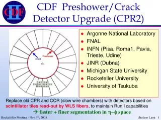
1.2.1: Preshower Status • Phototube status • Used to be the critical path item, ending in Oct 04 • Japan has accelerated orders, now delivery is March 04 • All phototubes will be ready for a Summer 04 installation • Detector status • All time-critical production parts ordered • Ready to start production in February 04 • 6-month production expected based on prototype • Should be ready for installation by Fall 2004
Preshower Installation • Cancellation of the silicon installation and its long shutdown has implications for other projects • Preshower installation is most affected • We have concluded that installation in the collision hall is possible. • Current installation schedule for both EM Timing and Preshower requires 10 weeks • Realistic manpower availability (40 hour weeks, 1 shift/day) • If cannot be completed in summer 04, will be completed during 2005 summer shutdown
1.2.2: EM Timing Status • Hardware is ready for installation • Hardware is 4 months ahead of schedule • All hardware finished & tested, ready for installation • All cables, splitters, ASDs and TDCs in hand • End-Plug installation completed, fully operational • 4 Central Wedges completed, fully operational • DAQ/online monitoring software fully working • Performance excellent, < 2 ns timing resolution • Installation procedures reviewed by experts • Installation to be completed in the next shutdown (2004)
1.3.1: TDC Status • New high speed TDC with Altera Stratix FPGAs • Excellent Chicago engineer team (built many CDF boards) • Design work started on Dec 2002 • Core firmware design finished on June 2003 • Firmware design reviewed by experts on July 2003 • Layout of board close to final • Backward compatible • Lots experience with TDC testing & commissioning within CDF
1.3.2: L2 Upgrade Status (I) Pulsar production started • Hardware 10 months ahead of original schedule • One motherboard, four mezzanine and one AUX design • All custom board prototypes designed&built last year • Board design extensively simulated + trace analysis • Have tested ALL interfaces in self-test mode (Tx Rx) • Core firmware fully developed (in CVS) and tested in beam • Has been used as RunIIa L2 muon interface board for data taking (interface with legacy Alpha processor) • Muon online DAQ/monitoring/offline software working • Production Readiness Review done (Nov. 07, 2003) • No blue wires on ALL prototypes, no revision needed Web page: http://hep.uchicago.edu/~thliu/projects/Pulsar
Pulsar Design modular/universal/self-testable Custom mezzanine AUX card Mezzanine slots • S-LINK • PCI • GbE Pulsar works up to 100MHz Top view Bottom view Pulsar design philosophy: able to interface with any user data with any link format (e.g. S-LINK or GbE) via mezzanine Many applications within & outside CDF (compatible with Atlas)
1.3.2: L2 Upgrade Status (II)Pulsar PC timing • Pulsar to PC round trip timing measured (w S-Link to PCI) • With Alpha L2 algorithm code running in Linux PC • Good performance (compare to that of old Alpha) Pulsar PC roundtrip timing PC vs old Alpha algorithm timing without L2 algorithm with L2 algorithm running 1.4GHz Linux PC 500MHz Alpha Tested with real L2 trigger data 2.4GHz Linux PC
1.3.3: Fast Track Trigger (XFT II) Status • Lots simulation work done • Have working XFT upgrade simulation • Hardware progress (in parallel with simulation) • Most interfaces design do not need to change, primary changes are in the firmware (algorithm) • All fully backward compatible • New Linker: firmware implemented & fully simulated • Finder&Linker board design begun • Start production by late 2004 • XFT II ready by summer 05 • Three new postdocs recently joined (Sept. 2003 -)
1.3.4: Event Builder Status • Technology decision made (Gigabit Ethernet) • VME to switch readout: VMIVME-7805 • GbE switch: Cisco 6509 • Well underway: • System design has been decided • Final system switch ordered • Readout test boards ordered • Expertise on board (from both CD and CDF) • Working prototype by Aug 2004 • Plan to have new system ready by Summer 2005
1.3.6: SVT Upgrade (SVT II) • Original plan was only to handle SVX IIb geometry • additional Merger boards + new Track Fitter boards • Now main motivation is to improve SVT efficiency with good timing (critical for high Luminosity L2 latency) • Redundant roads removal @ earlier stage less fits • Finer roads (larger Associative Memory or AM) less fits • Improve track fitting • Replace obsolete boards, add additional flexibility • Ensure good SVT performance all the way through 2009
1.3.6: SVT Upgrade (SVT II) • Phase One: (funded by operation money) • Use Pulsar as Road Warrior to remove redundant roads • RW firmware successfully tested on Pulsar last month • Ready for commissioning early 2004 (Pulsar production) • Phase Two: (AM++ funded by INFN R&D) • Replace old AM boards with new AM++ developed for LHC • Use Road Warrior to replace Hit Buffer & AM Sequencer (mostly firmware changes, replace obsolete boards, which also provides additional flexibility) • Replace Track Fitter (RunIIb money) • All backward compatible, can develop&tune standalone
Conclusions • Our baseline schedule will not change • We will work towards earlier completion • Our target is to install as much as possible in the summer 2004 and 2005 shutdowns. • We proposed a new baseline cost for the DOE MIE of $10.4M, accepted by the DOE on 8 December. By Fall 2005, CDF will be ready for operation at 3 1032cm-2s-1
Rebaselined Cost Estimate • Contingency per subproject is from 2002 low level estimate – *scaled by use to date • New DOE MIE total cost drops - $24,987K → $10,374K • All costs shown are total (M&S/Labor/Overhead), in current year $K
Pulsar pre-processors New L2: Pulsar Formation muon track L1 trigger SVT SLINK Buffer 0 & 3 Trigger supervisor muon PCISLINK PC 0 merger PC 3 L2 CAL SLINKPCI cluster PC 1 L2toTS merger PC 2 ShowMax Buffer 1 & 2 electron L2 Commissioning strategy • Pulsar’s self-testability allows us to • develop&tune the upgrade standalone • then run parasitically with CDF • aim at fall 2004 • minimal impact on data taking merger
Pulsar will be used as Road Warrior VME chip DataIO FPGA 1 P2 SVT inter-comm Lines(5): Master& Slave SRAM DataIO FPGA 2 SVT data in SVT input SVT data in SRAM SVT Control FPGA SVT data in SVT output SVT data out 2 SLINK Pulsar RW will also replace Hitter Buffer and AM Sequencer
Why do we want 4/5? 4/5 D0 4/4 D0
Upgrades: T(4/5) T(4/4) ! 4/5 – upgraded 4/5 – 4/4 After upgrade Current (4/5) s
SVT is running right now @4/5 4/5 Ghost removal 4.3 14.5 ROAD WARRIOR + AM ++ bring us back to the old 4/4 timing, with better efficiency!
Single Hit Road Detector Layers Superstrip What does the new Hardware do? Larger AM Hit Finders raw data from SVX front end Sequencer Associative Memory COT tracks fromXTRP x 12 phi sectors roads Road Warrior 12 fibers Track Fitter to Level 2 hits Merger hits Hit Buffer • How to speed up SVT: • Thinner roads (larger AM) less fits. • Road Warrior ghosts removal
AM++ • Replace old AM boards with 1 AM++/wedge • Increased pattern density: standard cell chips (2K [128] pattern/5x5 mm) • Potentially larger I/O bandwidth • Provide backward compatibility with older hardware • Can house potentially up to 1Mpattern!
AM++ schedule • New AM-board: summer 2004 (Pisa) • during summer 2004: test with FPGA chips (Pisa) • AM-chip design: july 2004 (Ferrara-Pisa) • first chip ~2 months october • New LAMB: assemble AM-chip in october 2004 • (Pisa) • test chip + board: october – december 2004 • (Pisa-Ferrara) • Mass production: beginning 2005 (Pisa-Ferrara) • install: summer 2005 (Pisa-Ferrara)
Impact on data taking • Boards can be completely developed and tested in test-stands • Algorithm development & tuning may require some test runs • Overall the experiment dead time will come from: • Boards swapping • Development/modification of online code • Everything will be back-compatible: virtually no point of no-return!
Flexibility • The larger AM bank allows new strategies: • Narrower patterns to improve timing • Trigger bit dependent patterns • (L1) Lepton seeded pattern recognition • Standalone Si tracking • As an example we tried to merge 3. And 4. To build a forward z trigger!
In a glimpse.. • Efficiency @ L2: study Z0 from data • Back. Rejection: L1 backup from data
Upgrading the Track Fitter • The current TF cannot handle 1Mpattern (current limit is [16x]32K patterns) • Current design is based on ageing components at their fullest • it would not accommodate: • Handling of a large pattern bank • Handling of different patterns for different trigger strategies • Handling of >4 detector layers (e.g. if we want to add lepton ID/TOF information to the SVT fit)
SVT upgrade INFN Pisa • Annovi, A. Bardi, P. Catastini, M. Dell’Orso, P. Giannetti, L. Ristori, F. Spinella INFN Ferrara Damiani, Sartori, R. Tripiccione, Cotta, Chiozzi INFN Trieste S. Belforte LBNL A. Cerri
Back up slides • Man power (just in case they ask) • need a full list of names for each project, but couldn’t find the full list some projects…. Experts, please help. • Motivation (just in case we need to remind people), although this talk is just for STATUS. • misc Backup slides are for possible questions, most of them will not show up in the actual pdf file sent to PAC The part will be sent to PAC is slide 1-17
University of Tsukuba INFN (Pisa, Rome) JINR (Dubna) Argonne National Laboratory Michigan State University Rockefeller University FNAL Texas A&M INFN (Frascati) University of Chicago University of Michigan Argonne National Lab FNAL Calorimetry Upgrade Steve Kuhlmann, Level-2 Manager Joey Huston, Level-3 Manager Preshower Dave Toback, Level-3 Manager EM Timing Preshower/Crack Electromagnetic Timing
TDC Upgrade: people • University of Chicago • Engineers: Harold Sanders, Mircea Bogdan • Physicist: Henry Frisch • Fermilab • Physicist: Ting Miao • Engineers: Looking for new people to get involved
XFT Upgrade: people • Ohio State University • Richard Hughes, Kevin Lannon(pd), Ben Kilminster(pd), Brain Winer • University of IIIinois • Mike Kasten(eng), Suzanne Levine(gs), Ryan Mokos (eng), Kevin Pitts, Greg Veramendi(pd) New groups are getting involved: • Purdue University (Matthew Jones et al.) • Rutgers University (John Conway, Amit Lath et al.) • Fermilab (engineering/technician support)
Pulsar project • Related to CDF L2 decision crate upgrade: • ANL • R. Blair, J. Dawson, B. Haberichter, J. Schlereth, J. Proudfoot • FNAL • R. Demaat, M. Hakala, R. Kivilahti, J. Lewis, C. Lin, T. Liu, T. Masikkala, • F. Marjamaa, J. Patrick, S. Pitkanen, B. Reisert, P.Wilson • Univ. of Chicago • M. Bogdan, Y. Kim, W. Fedorko, H. Frisch, S. Kwang, V. Rusu, H. Sanders, • M. Shochet • Upenn • K. Hahn, P. Keener, J. Kroll, C. Neu, F. Stabenau, R. Van Berg, D. Whiteson, • P. Wittich The project first started as a project (with few people) to build a test-stand tool …
Pulsar has attracted many good young people new generation of L2 experts ! • After prototype success last year, many young people joined the project this year: • Burkard Reisert (FNAL RA, from H1): Jan. 2003 - • Cheng-Ju Lin (FNAL RA, SLD): Jan. 2003 - • Chris Neu (Upenn postdoc, CDF): Oct. 2003 – • Vadim Rusu (Chicago postdoc, SNOW): Oct. 2003 – • Dan Whiteson (Upenn postdoc, D0): Dec. 2003 – • Shawn Kwang (Chicago student, 2rd year): Jan. 2003 – • Wojciech Fedorko (Chicago, first year): Oct. 2003 - • Kristian Hahn (Upenn, third year): Jan. 2003 – • Hans Stabenau (Upenn, 2rd year): May 2003 -
Event Builder Upgrade Core team: Markus Klute (MIT) Bruce Knuteson (MIT) Ron Rechenmacher (Fermilab) Sham Sumorok (MIT) Steve Tether (MIT)
Maintain capabilities of current Preshower detector, used in over 100 papers. Preshower expected to suffer high occupancy and aging effects in Run IIB. Preshower and Crack detectors expected to provide 5-10% Jet Energy Resolution improvement, part of the 20-30% needed improvement for the Higgs search. Electromagnetic timing needed to reject photon backgrounds from cosmic rays, in new physics searches such as SUSY. Calorimetry Upgrade Motivation
Electromagnetic Timing • Virtually identical to existing system on hadron calorimeter • Re-use electronics and well-established technologies • Add splitters for CEM. PEM already readout-ready • Build more ASD’s • Recycle TDC’s, crate and tracer. Purchase new power supply and processor
Motivation • The DAQ/Trigger upgrades presented here are driven exclusively by our Run IIb trigger and data acquisition needs to carry out our high-pT physics program • Our current level of understanding is based upon • Run IIa data: L 2x1031 cm-2 s-1, ~1 interaction per crossing • Run I data: L ~2x1031 cm-2 s-1, ~2 interactions per crossing • We are extrapolating to Run IIb • L = 2x1032 cm-2 s-1 w/396ns bunch spacing (~5 int/beamX) • Due to significant uncertainties in extrapolation, and a desire to be prepared for success, we have evaluated our system for: L = 4x1032 cm-2 s-1 w/396ns bunch spacing (~10 int/beamX)
Trigger Strategy • Focus on Higgs & high pT searches • Know that triggers needed for these modes will allow for many beyond Standard Model searches • General requirements: • High pT electrons and muons • Associated WH/ZH modes, also tWb • Missing ET triggers • ZH with , modes with taus • b-jet triggers • , b-jets tagged by displaced tracks • Calibration triggers • , J/+, photons
Summary of Run IIb specifications • Level 1 Accept rate: >25kHz (spec 50kHz) • deadtimeless • Level 2 Accept rate: 750 Hz bursts to 1.1kHz • L2 processing deadtime < 5% • readout deadtime (on L2A) < 5% • Level 3 Accept rate: 85Hz • Event builder rate: 400MB/s • Output data rate: 40MB/s • Reminder: trigger & bandwidth rates estimated based upon Run IIa, significant underestimate possible (assumes linear growth in fake contribution)
CDF Data Acquisition System • Level 1 trigger • pipelined and “deadtimeless” • fully synchronous • designed for 132ns operation • on L1A, write data to 1 of 4 local L2 buffers • Level 2 trigger • asynchronous • L1 + supplemental info • Level 3 trigger • full detector readout • PC farm runs reconstruction • output to mass storage
Trigger/DAQ Upgrades for Run IIb General considerations: • upgrades “targeted” to specific needs • e.g. COT TDCs replaced, but remaining COT readout (ASDQ, repeaters) unmodified • retain existing infrastructure • cables, crates unchanged • I/O protocols, timings retained • upstream/downstream components unchanged • upgrades plug compatible with existing components • take advantage of knowledge & experience • will aid in commissioning
TDC Replacement Limitations of current system: • TDC on-board data processing • existing system performs hit processing after L2A • processing time (=deadtime) grows with # of hits • COT occupancy higher than expected • Run IIa processing time too large for Run IIb • VME readout • 16 TDCs per crate read out serially by VME block transfer • current VME transfer rate 14MB/s with additional overhead per board • Run IIa, 300Hz…falls to ~150Hz (!) in Run IIb • Data transfer • TRACERTAXIVRB link provides bandwidth limitation • maximum TAXI VRB is <12MB/s…Run IIb requires 14MB/s
TDC (on-board) processing time [time after L2A] Now: slowest TDC >650s/event Need ~360s to achieve 1kHz L2A rate VME readout Currently: ~ 500s per crate Run IIb: x10 more data >1ms Data transfer Run IIb: expect 14MB/s, TAXI link limited to <12MB/s Internal CDF TDC Review committee convened in June Conclusion: existing COT TDCs + VME readout system cannot maintain necessary L2A rate in Run IIb TDC system must be replaced OR significant modifications to the DAQ & infrastructure must take place Run IIb TDC Performance • Specification: entire TDC readout must be completed within 600s to handle 1.1kHz rate 14MB/s.
New TDC Design • Address on-board processing deadtime by moving hit processing into the L1L2 transition • “hide” hit processing behind L2 trigger • Address VME and Readout problems via bypassing the VMETRACERTAXI • Keep existing data path as a backup (commissioning) • Maintain other pieces of DAQ chain (VRB EVB) • Design exclusive to COT system, reduces constraints • Run IIa TDC will continue to work well for other systems (muons, hadron timing, CLC)
TDC Specifications • Backward compatible with existing system • No change to COT front-end, cables or calibration • No change to track trigger (XFT) interface • Accept CDF specific signals from CDF_CLOCK/TRACER • Must handle the following rates • 50kHz L1A, 1.1kHz L2A • Readout time below 500s with 20kB/crate • Allow for on-board data compression • Perform hit finding for track trigger • “TDC Specifications” document provides details