Download
1 / 7
70 likes | 173 Views
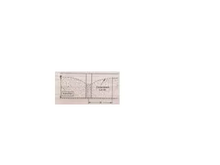
Positron Source AD & I Report. Jim Clarke ASTeC & Cockcroft Institute Daresbury Laboratory. Explore Parameters …. Wanming Liu, Wei Gai, ANL. 0.4 rad length Ti target & QWT Yield at 125MeV with DR acceptance Assume B = 1T (conservative) For yield of 1.5 @ 150GeV need ~230m undulator

E N D
Positron Source AD & I Report Jim Clarke ASTeC & Cockcroft Institute Daresbury Laboratory
Explore Parameters … Wanming Liu, Wei Gai, ANL • 0.4 rad length Ti target & QWT • Yield at 125MeV with DR acceptance • Assume B = 1T (conservative) • For yield of 1.5 @ 150GeV need ~230m undulator • For yield of 2.0 @ 250GeV need ~100m undulator 150 GeV, QWT, 100m undulator 250 GeV, QWT, 100m undulator Global Design Effort
Low Energy Running Plot shows RDR case vs E Need new plots for SB2009 cases but plot suggests yield drops by ~x2 between 150 GeV and 125 GeV What yield is needed below 150 GeV? Guidance needed !
Low Electron Energy Operation For calibration purposes (Z-pole) the auxiliary source will be able to provide intensity at the few % level At some energy below 150 GeV the ILC could operate in a pulse sharing mode Positrons are generated at high energy but at half rep rate Electrons are transported at the low energy to the IP at half rep rate This option gives half the number of bunches at the IP Initial studies reported this week suggest may be practical to transport low & high energy beams through linac but definitely not ideal! Separation of two beams not clear – where to dump high E beam, low E beam bypass around und?
Low Electron Energy Operation Alternatively, an undulator of length sufficient for 125 GeV operation could be installed Then a second injector could be installed at the 125 GeV point in the linac and a bypass line This would allow one beam to generate positrons at 125 GeV and a second beam (covering 50 to 125GeV) could be transported to the BDS No loss in luminosity at any energy Electrons with energy 50 to 125 GeV Positrons Linac 1 Linac 2 Electrons @ 125 GeV for undulator then dumped Electrons go through both linac sections for energies >125GeV
Positron Source – AD&I 3 D Layout Positron Source ‘AUX Source’ region. Tune-Up Dump and Diagnostics Section Remote Handling RTML 2 off Cryomodules at 12.6m with Quad, in Line with Photon Beam, approx. 30MeV/m Thermionic Gun, Bunchers, Diagnostics, 2 off Standing Wave Accelerators (12 MeV/m), Diagnostic Section and Tune-Up Dumps. BDS ‘Dogleg’ I.P. Direction Photons coaxial with cryomodules, OK? Photon Beam Pipe N.Collomb
AD&I Wrap up : electron source 2 minor issues: 1. Length of allocated electron source space Tunnel ~ 2 km but need only ~ 500m 2. Length of eLTR due to required offset Need to review / extend lattice file Time needed for resolution: ~ 1 month.