Download

1 / 19
1.09k likes | 3.06k Views
TURBOMACHINES Chapter 5 CENTRIFUGAL compressors & axial flow compressors. Introduction. Compressor is a device used to produce large pressure rise ranging from 2.5 to 10 bar or more. A single stage compressor generally produce a pressure rise up to 4 bar.

E N D
TURBOMACHINESChapter 5CENTRIFUGAL compressors & axial flow compressors
Introduction • Compressor is a device used to produce large pressure rise ranging from 2.5 to 10 bar or more. • A single stage compressor generally produce a pressure rise up to 4 bar. • In general centrifugal compressors may be known as fan, blower, supercharger etc, depending upon the need to be served. • Fans are low pressure compressors and blowers are medium pressure compressors.
Elements of a centrifugal compressor • It mainly consists of (i) inlet casing with the converging nozzle (ii) the impeller (iii) the diffuser and (iv) the outlet casing.
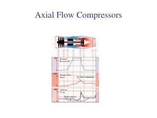
Variation of pressure and velocity • Fig below shows the variation of pressure and velocity in a centrifugal compressor.
Velocity triangle at the Eye Hub and Tip • In ideal condition the fluid enters the eye section radially with no whirl component. • The velocity remains constant from hub to tip of the eye. • The tangential velocities of the impeller at the hub (root) and the tip of the eye are calculated based on the corresponding hub and tip diameters of the eye respectively.
Different vane shape • The impellers may be classified depending on the exit angle β2 into (i) Backward curved vanes, (ii) Radial vanes and (iii) Forward curved blades.
The above equation is known as H-Q characteristic curve for the centrifugal fan, blower and compressor. • The value of K1 represents the K.E of the fluid moving in the tangential tip speed of the impeller and the constant K2 represents the slope the H-Q curve which may be positive, zero or negative for fixed value of β2. • The H-Q relationship can be obtained as in fig.
Where Cd is the total drag coefficient. • Total loss in the system, • Actual head produced can therefore be obtained by deducing these losses from ideal head developed by the machine, i.e., • Fig shows the actual characteristic of C.F compressor,
Slip and Slip Co-efficient • It is assumed that the velocities are constant over the cross sectional area. • But in actual practice this assumption is not correct as shown if fig,
Surging • The phenomenon of momentary fluctuations in head and discharge due to unsteady flow, flow reversal and vibration at low flow rate is called surging.
Pre-rotation or Pre-whirl • We know that the velocity at inlet have more effect on Mach number at inlet. • The relative velocity at the inlet should be minimum, which reduces the Mach number for a given eye tip diameter. • For a fixed eye tip diameter the Mach number can be reduced by providing pre-whirl at the inlet using guide vanes.
Diffuser • Diffuser is used in the centrifugal compressor to convert large kinetic energy of the fluid exiting from the impeller to useful fluid or pressure energy. • Diffuser may be (i) Vaneless type (ii) Vaned type
Axial flow compressor • It is essentially an axial flow turbine driven in the reverse direction except that in order to achieve a sufficiently high efficiency, it is necessary to design blades by taking extreme care.
The general velocity triangles at inlet and outlet are as shown in fig.
If the reaction is not equal to 50% then the velocity triangles are unsymmetric and then design is on whether absolute velocity of air at rotor inlet or outlet is axial. • The velocity triangles for the two cases are as shown in fig.
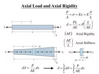
Work done & efficiencies of compressor • The actual work is given by • The ideal work • Then the static-to-static efficiency is defined as
Work Done Factor • Fig shows the axial velocity distributions in the first and last stage of a multistage axial compressor. • The degree of distortion in the axial velocity distributions will depend on the number of the stages. • On account of this, the axial velocity in the hub and tip regions is much less than the mean value, whereas in the central region its value is higher than the mean.
Form Euler’s equation, • In terms of blade angles, w.r.t tangential direction is given by • From geometry, • Therefore,