Download
1 / 38

E N D
CAPP GUIDELINE - H2S RELEASE RATE ASSESSMENT FOR A WELLCommittee Members:Todd Wilson BEHR Energy Services Ltd.Irakli Kaceli Energy Resources Conservation BoardTom Smith Devon Canada CorporationRay Featherstone Devon Canada CorporationJohn Carroll Gas Liquids Engineering Ltd.David Dunn Fekete Associates Inc.
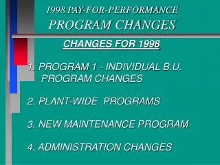
CHANGES FROM 1998 GUIDELINES • Removal of exemption area maps • Improved organization • Address changes in regulatory practices and industry operations • Address committee objectives
H2S RR COMMITTEE OBJECTIVES • Bridge the gap between written and what is accepted • Elaborate search area requirements • Address stimulated horizontals • Clarify net pay adjustment requirements • Address acid gas injection guidelines • Alignment with Alberta and BC regulations • Guidance for ERCBH2S
CAPP GUIDELINES APPROACH • Start with a conservative (high) estimate • Highest H2S sample and AOF sample used for each formation • Outline methods through data qualification and technical analysis that may reduce the H2S release rate • Emphasis on good professional judgment • CAPP Guidelines - a reference document – it does not exclude other approaches
DETAILED ANALYSIS CONSIDERATIONS • Does the EPZ include residents or areas with high public usage? • Is the well within 5.0 km of an urban density development (50 or more dwellings)? • Is the well classified as Critical or Special?
GEOLOGICAL DISCUSSION • Outlines the play – helps establish the analogs • Well may be down dip of a gas/oil contact • Prospective reservoir may be in a specific pool or similar to a specific pool • Well may be targeting an off-reef feature • Distinctions of gas cap vs oil leg data • Zones may be low and wet or tight
GEOLOGICAL MAPPING • Generally 3 township by 3 township area • Flexibility here – depends on well density • Grid size illustrates geological trends • Maps for primary and secondary zones as noted in Schedule 4 (PURPOSE OF WELL) • Data collected for other zones with H2S potential (not on Schedule 4)
GEOLOGICAL MAPPING (cont’d) • Choose map type best illustrating geology: • Net pay isopach • Gross pay isopach • Structure contour, etc. • Include dip-oriented cross sections for foothills wells
DRILLING CASE • Multiple strings - prepare calculations for each hole section – Use highest release rate of any of the hole sections • Commingling of zones within hole section • Include 15-m overhole • Adjustment to unstimulated conditions • If a gas cap is encountered (above an oil target) consider gas cap flow capability • Vertical flow analysis may be conducted
DRILLING CASE (cont’d) • Shallow wells (terminating above Mannville) • EPZs generally do not extend much beyond lease • Deep wells (terminating below top of Mannville) • Shallow zones need not be included if deeper zones have an H2S release rate potential (unless the shallow zone is known to significantly impact the H2S release rate)
COMPLETION/SERVICING CASE • Only completed zones evaluated • Usually based on highest release rate zone unless: • Company does not have rights to the zone • Another producing well in same spacing unit • Company will revisit stakeholders • Stimulated conditions applied
COMPLETION/SERVICING CASE • Typical flow path: • Wellhead off – Up Casing • Wellhead on with packer in place – Up Tubing (This is new) NOTE: Consider the wellhead off case to ensure appropriate design (Would the well be Critical with wellhead off?)
PRODUCING CASE • Only completed zones incorporated • Used to set Level of Well for setback restrictions • Usually based on highest release rate zone • Incorporates wellbore design • Once completed, adjust to actual conditions
WELLS DRILLED IN EXISTING POOL • Flow and Gas data sampling may be restricted to the single pool • Gas sampling • No minimum number of valid gas samples • Use all of the gas samples in pool unless: • H2S trend in pool can be clearly mapped • At least five of the closest wells are referenced • If pool samples are poor use 5 samples outside of pool
WELLS DRILLED IN EXISTING POOL (cont’d) • Flow data sampling • Five valid flow data points are required • If data is poor in quality or has less than five tests, then samples from outside of pool should be considered
WELLS DRILLED OUTSIDE EXISTING POOL • Gas and Flow Data Sampling • Generally five data samples required • All samples within 5 km should be included unless they can be geotechnically discounted • Highest H2S from multiwell pool within review area should be included in data sampling • A minimum of three pools is preferable if reasonable analogs exist. Fewer pools acceptable if geologically supported.
WELLS DRILLED OUTSIDE EXISTING POOL (cont’d) • Gas and Flow Data Sampling • Fewer than five data points may be acceptable if analogous data is limited and: • Data is good in quality • Formation in question is not a significant contributor of the overall H2S release rate or the well is in a remote area with no site-specific ERP requirements
GAS SAMPLES • Order of Accuracy • Sample from first stage separator • Wellhead sample • Downhole samples after well is on production • Downhole samples from RFTs, MDTs • Solution gas samples may be excluded if flow data is from gas cap • Gas cap samples should not be considered if flow data is from an oil leg
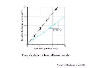
FLOW ADJUSTMENT METHODS • Determining Sandface AOF from test data • (Rawlins, Vogels, etc) • Adjusting for reservoir pressure differences • Adjusting for differences in net pay • Stimulated vs unstimulated • Deviation and horizontal wells • Sandface vs wellhead AOF
GAS FLOW RATE AOF From Rawlin’s Equation Where: • Pr = Reservoir Pressure (kPa) • Pwf = Flowing Bottomhole Pressure (kPa) • AOF = Absolute Open Flow Potential (m3/d) • Gas Test Rate (m3/d) • n = inverse slope on isochronal (log-log) plot n is generally assumed = 1.0 unless multipoint data is available
GAS FLOW RATE AOF • Use extended data rather than stabilized data • Use value of 1.0 for single-point data unless a review supports a different value
Stabilized AOF Extended AOF Transient AOF 200 500 100 1000
OIL - ASSOCIATED GAS AOF • For GOR < 2000 m3/m3 – Sandface AOF Saturated Reservoir From Vogel’s Equation Where: • Pr = Reservoir Pressure (kPa) • Pwf = Flowing Bottomhole Pressure (kPa) • AOFoil = Absolute Open Flow Potential (m3/d) • GOR = Gas / Oil Ratio (m3/ m3) • qt = Oil Rate • AOFgas = AOFoil x GOR (NOTE: GOR reference is from the same time (test data) that the qt is referenced.)
OIL - ASSOCIATED GAS AOF • For GOR ≥ 2000 m3/m3 – Sandface AOF Saturated Reservoir From Vogel’s Equation Where: • Pr = Reservoir Pressure (kPa) • Pwf = Flowing Bottomhole Pressure (kPa) • AOFgas = Absolute Open Flow Potential (m3/d) • AOFgas = AOFoil x GOR (NOTE: GOR reference is from the same time (test data) that the qt is referenced.)
STIMULATED vs. UNSTIMULATED FLOW Where: • AOF = Absolute Open Flow Potetntial (m3/d) • re = drainage radius (m) • rw = wellbore radius (m) NOTE: ln(re/rw)+S = ln( re/(rw(e-S)))
ADJUSMENT TO NET PAY (h) • AOFproposed = (hproposed/hanalog)x AOFanalog • Applied to the Primary and Secondary formations listed on Schedule 4 – “Purpose of Well” • Not applicable for thick reservoirs requiring fracture stimulation where fracture height would not grow to full height of reservoir • Generally not required for carbonates
RESERVOIR PRESSUREADJUSTMENT FOR GAS WELLS Where: AOFproposed & AOFanalog= original and adjusted AOF potentials Zanalog & Zproposed = original and adjusted compressibility factors µanalog & µproposed = original and adjusted viscosity of gas Pranalog & Prproposed = original and adjusted reservoir pressures n = inverse slope of isochronal data
RESERVOIR PRESSUREADJUSTMENT FOR OIL WELLS Where: AOFoil(proposed) & AOFoil(analog)= original and adjusted AOF potentials Pr(analog) & Pr(proposed) = original and adjusted reservoir pressures
DEVIATED WELLS (Deviation >30d) where • a = (kh/kv)0.5 • Y = [(kv/kh) + (h/L)2 (kh-kv)/kh]0.5 • Where: • L = producing length (m) • kh & kv = horizontal and vertical permeability (md) • rw & re = wellbore radius and drainage radius (m) • h = reservoir thickness (m)
HORIZONTAL WELLS(Matrix Drainage) where: • AOFhorizontal = AOF of proposed (horizontal) well (m3/d) • AOFvertical = AOF of analog (vertical) well (m3/d) • rev = drainage radius of vertical well (m) • reh = drainage radius of horizontal well (= ½ L + rev) • rwv = wellbore radius of vertical well (m) • rwh = wellbore radius of horizontal well (m) • spseudo = skin effect due to horizontal wellbore
HORIZONTAL WELLS (cont’d)(Matrix Drainage) Where: • rwh = wellbore radius of the horizontal well • a = (anisotropy ratio) • e = eccentricity of the horizontal well (vertical distance between middle of the reservoir and well axis - it is recommended not to use e values greater than 0.25h) (m) • h = reservoir thickness (m) • kh = permeability in the horizontal direction (md) • kv = permeability in the vertical direction (md) • L = producing length of the well (m)
HORIZONTAL WELLS(Fractured Drainage) • Consider the horizontal lateral as a collection pipeline that are connecting individual frac treatments Two options: • Proportion the number of fracs proposed in the horizontal well to number of fracs in other stimulated horizontals or vertical wells • Proportion the length of the horizontal well • Assumes the stimulation efficiency is proportionate to length of lateral
ACID GAS INJECTION • Acid gas may either be gaseous or dense phase at reservoir conditions • May undergo phase change in reservoir or wellbore • As for conventional wells, the sandface AOF and tubular performance must each be assessed to determine the wellhead AOF
ACID GAS INJECTION (cont’d) Tubing performance curve – gas phase Effect of dense phase on tubing performance