Download
1 / 43
430 likes | 454 Views
Learn how to go from switches to logic gates to logic circuits, exploring truth tables, identity laws, logic circuit minimization, algebraic manipulations, and maximizing efficiency with Karnaugh Maps. Discover the basics with Professor Hakim Weatherspoon at Cornell University.

E N D
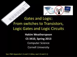
Gates and Logic:From Transistorsto Logic Gates and Logic Circuits Prof. Hakim Weatherspoon CS 3410 Computer Science Cornell University [Weatherspoon, Bala, Bracy, and Sirer]
Goals for Today • From Switches to Logic Gates to Logic Circuits • Logic Gates • From switches • Truth Tables • Logic Circuits • From Truth Tables to Circuits (Sum of Products) • Identity Laws • Logic Circuit Minimization • Algebraic Manipulations • Truth Tables (Karnaugh Maps) • Transistors (electronic switch)
A switch Acts as a conductor or insulator. • Can be used to build amazing things… The Bombe used to break the German Enigma machine during World War II
Basic Building Blocks: Switches to Logic Gates + Truth Table A - B + A - B
Basic Building Blocks: Switches to Logic Gates • Either (OR) • Both (AND) Truth Table A - OR B A - AND B
Basic Building Blocks: Switches to Logic Gates • Either (OR) • Both (AND) Truth Table A - OR 0 = OFF 1 = ON B A - AND B
Basic Building Blocks: Switches to Logic Gates A OR B George Boole (1815-1864) A • Did you know? • George Boole: Inventor of the idea of logic gates. He was born in Lincoln, England and he was the son of a shoemaker in a low class family. AND B
Takeaway • Binary (two symbols: true and false) is the basis of Logic Design
Building Functions: Logic Gates • NOT: • AND: • OR: • Logic Gates • digital circuit that either allows a signal to pass through it or not. • Used to build logic functions • There are seven basic logic gates: AND, OR, NOT, NAND (not AND), NOR (not OR), XOR, and XNOR (not XOR) [later] A NAND: A B A B NOR: A B A B
Goals for Today • From Switches to Logic Gates to Logic Circuits • Logic Gates • From switches • Truth Tables • Logic Circuits • From Truth Tables to Circuits (Sum of Products) • Identity Laws • Logic Circuit Minimization • Algebraic Manipulations • Truth Tables (Karnaugh Maps) • Transistors (electronic switch)
Next Goal • Given a Logic function, create a Logic Circuit that implements the Logic Function… • …and, with the minimum number of logic gates • Fewer gates: A cheaper ($$$) circuit!
Logic Gates NOT: AND: OR: XOR: A A NAND: A B B NOR: A A B B XNOR: A A B B
Logic Implementation • How to implement a desired logic function?
Logic Implementation • How to implement a desired logic function? • Writeminterms • sum of products: • OR of all minterms where out=1
Logic Equations • NOT: • out = ā = !a = a • AND: • out = a ∙ b= a & b = a b • OR: • out = a + b = a | b = a b • XOR: • out = a b = a + āb • Logic Equations • Constants: true = 1, false = 0 • Variables: a, b, out, … • Operators (above): AND, OR, NOT, etc. NAND: • out = = !(a & b) = (a b) NOR: • out = = !(a | b) = (a b) XNOR: • out = = ab + • .
Identities • Identities useful for manipulating logic equations • For optimization & ease of implementation a + 0 = a + 1 = a + ā = • a ∙ 0 = • a ∙ 1 = • a ∙ ā =
Identities • Identities useful for manipulating logic equations • For optimization & ease of implementation = = a + a b = a(b+c) = =
Goals for Today • From Switches to Logic Gates to Logic Circuits • Logic Gates • From switches • Truth Tables • Logic Circuits • From Truth Tables to Circuits (Sum of Products) • Identity Laws • Logic Circuit Minimization – why? • Algebraic Manipulations • Truth Tables (Karnaugh Maps) • Transistors (electronic switch)
Checking Equality w/Truth Tables circuits ↔ truth tables ↔ equations Example: (a+b)(a+c) = a + bc
Takeaway • Binary (two symbols: true and false) is the basis of Logic Design • More than one Logic Circuit can implement same Logic function. Use Algebra (Identities) or Truth Tables to show equivalence.
Goals for Today • From Switches to Logic Gates to Logic Circuits • Logic Gates • From switches • Truth Tables • Logic Circuits • From Truth Tables to Circuits (Sum of Products) • Identity Laws • Logic Circuit Minimization • Algebraic Manipulations • Truth Tables (Karnaugh Maps) • Transistors (electronic switch)
Karnaugh Maps How does one find the most efficient equation? • Manipulate algebraically until…? • Use Karnaugh Maps (optimize visually) • Use a software optimizer For large circuits • Decomposition & reuse of building blocks
Minimization with Karnaugh maps (1) • Sum of minterms yields • out = c + bc + a + ac
Minimization with Karnaugh maps (2) • Sum of minterms yields • out = c + bc + a + ac • Karnaughmap minimization • Cover all 1’s • Group adjacent blocks of 2n 1’s that yield a rectangular shape • Encode the common features of the rectangle • out = a + c ab c 00 01 11 10 0 1
Karnaugh Minimization Tricks (1) ab c 00 01 11 10 • Minterms can overlap • out = • Minterms can span 2, 4, 8 or more cells • out = 0 1 ab c 00 01 11 10 0 1
Karnaugh Minimization Tricks (2) ab cd 00 01 11 10 00 • The map wraps around • out = • out = 01 11 10 ab 00 01 11 10 cd 00 01 11 10
Karnaugh Minimization Tricks (3) ab cd 00 01 11 10 00 • “Don’t care” values can be interpreted individually in whatever way is convenient • assume all x’s = 1 • out = • assume middle x’s = 0 • assume 4th column x = 1 • out = 01 11 10 ab cd 00 01 11 10 00 01 11 10
Minimization with K-Maps • (1) Circle the 1’s (see below) • (2) Each circle is a logical component of the final equation • =a+c ab c 00 01 11 10 0 1 Rules: Use fewest circles necessary to cover all 1’s Circles must cover only 1’s Circles span rectangles of size power of 2 (1, 2, 4, 8…) Circles should be as large as possible (all circles of 1?) Circles may wrap around edges of K-Map 1 may be circled multiple times if that means fewer circles
Multiplexer a b d • A multiplexer selects between multiple inputs • out = a, if d = 0 • out = b, if d = 1 • Build truth table • Minimize diagram • Derive logic diagram
Takeaway • Binary (two symbols: true and false) is the basis of Logic Design • More than one Logic Circuit can implement same Logic function. Use Algebra (Identities) or Truth Tables to show equivalence. • Any logic function can be implemented as “sum of products”. Karnaugh Maps minimize number of gates.
Goals for Today • From Switches to Logic Gates to Logic Circuits • Logic Gates • From switches • Truth Tables • Logic Circuits • From Truth Tables to Circuits (Sum of Products) • Identity Laws • Logic Circuit Minimization • Algebraic Manipulations • Truth Tables (Karnaugh Maps) • Transistors (electronic switch)
Silicon Valley & the Semiconductor Industry • Transistors: • Youtube video “How does a transistor work” https://www.youtube.com/watch?v=IcrBqCFLHIY • Break: show some Transistor, Fab, Wafer photos
Transistors 101 Gate Source Drain — Insulator Gate + Source Drain - + + + + + + + - N-type P-type P-type - - - + + - - P-type channel created - + + + + + - - - - - - Insulator - - - - - - + - - - - + + + + - - + + + - - - N-type P-type P-type - - - - + + + + - + + - P-Transistor On P-Transistor - - - - - - - - - - - - - - N-Type Silicon: negative free-carriers (electrons) P-Type Silicon: positive free-carriers (holes) P-Transistor: negative charge on gate generates electric field that creates a (+ charged) p-channel connecting source & drain N-Transistor: works the opposite way Metal-Oxide Semiconductor (Gate-Insulator-Silicon) • Complementary MOS = CMOS technology uses both p- & n-typetransistors - - - - - Off
CMOS Notation On/Closed On/Closed Off/Open Off/Open 0 0 1 1 N-type P-type Gate input controls whether current can flow between the other two terminals or not. Hint:the “o” bubble of the p-type tells you that this gate wants a 0 to be turned on gate gate
2-Transistor Combination: NOT CMOS Inverter : • Logic gates are constructed by combining transistors in complementary arrangements • Combine p&n transistors to make a NOT gate: power source (1) power source (1) power source (1) — + p-gate p-gate closes p-gate stays open 1 0 0 1 output input n-gate — + n-gate closes n-gate stays open ground (0) ground (0) ground (0)
Inverter Vsupply (aka logic 1) Function: NOT Symbol: Truth Table: in out in out (ground is logic 0)
NOR Gate Vsupply • Function: NOR • Symbol: • Truth Table: A a B out b out B A
Building Functions (Revisited) a • NOT: • AND: • OR: • NAND and NOR are universal • Can implement any function with NAND or just NOR gates • useful for manufacturing a b a b
Logic Gates • One can buy gates separately • ex. 74xxx series of integrated circuits • cost ~$1 per chip, mostly for packaging and testing • Cumbersome, but possible to build devices using gates put together manually
Then and Now http://techguru3d.com/4th-gen-intel-haswell-processors-architecture-and-lineup/ • The first transistor • One workbench at AT&T Bell Labs • 1947 • Bardeen, Brattain, and Shockley • Intel Haswell • 1.4 billion transistors, 22nm • 177 square millimeters • Four processing cores https://en.wikipedia.org/wiki/Transistor_count
Then and Now https://www.computershopper.com/computex-2015/performance-preview-desktop-broadwell-at-computex-2015 • The first transistor • One workbench at AT&T Bell Labs • 1947 • Bardeen, Brattain, and Shockley • Intel Broadwell • 7.2 billion transistors, 14nm • 456 square millimeters • Up to 22 processing cores https://en.wikipedia.org/wiki/Transistor_count
Big Picture: Abstraction • Hide complexity through simple abstractions • Simplicity • Box diagram represents inputs and outputs • Complexity • Hides underlying NMOS- and PMOS-transistors and atomic interactions Vdd a in out d out b Vss a d out out in b
Summary • Most modern devices made of billions of transistors • You will build a processor in this course! • Modern transistors made from semiconductor materials • Transistors used to make logic gates and logic circuits • We can now implement any logic circuit • Use P- & N-transistors to implement NAND/NOR gates • Use NAND or NOR gates to implement the logic circuit • Efficiently: use K-maps to find required minimal terms