Download
1 / 16
320 likes | 784 Views
Logic Gates. Introduction. Computers are electronic devices. The basic elements of a computer control the flow of electricity. Controlling the flow of electricity in a computer allows us to make decisions and perform calculations. A Gate.

E N D
Introduction • Computers are electronic devices. The basic elements of a computer control the flow of electricity. • Controlling the flow of electricity in a computer allows us to make decisions and perform calculations
A Gate • A gate is a device that performs a basic operation on electrical signals. • A gate accepts one or more input signals and produces a single output signal. • A low voltage signal is shown as a 0 (zero) • A high voltage signal is shown as a 1 (one) • Gates are combined into circuits to perform tasks such as arithmetic and store values.
Notation when describing Gates • Boolean Expressions - is an expression that results in a boolean value, that is, in a value of either true or false. • Logic diagrams • This is a graphical version of a circuit • Truth tables • Defines the function of a gate by listing all the possible input combinations along with the corresponding output
6 Types of Gates • NOT • AND • OR • XOR • NAND • NOR
NOT Gate • A NOT gate accepts one input signal and produces one output signal. Truth Table Logic Diagram Symbol Boolean Expression X = A ’ A NOT gate is sometimes referred to as an inverter because it inverts (reverses) the input value
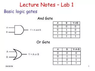
AND Gate • An AND gate accepts two input signals and produces one output signal. Truth Table Logic Diagram Symbol Boolean Expression X = A B The values of both input signals determine what the output signal will be.
OR Gate • An OR gate accepts two input signals and produces one output signal. Truth Table Logic Diagram Symbol Boolean Expression X = A + B The values of either signals determine what the output signal will be.
XOR Gate • An XOR (exclusive OR) gate accepts two input signals and produces one output signal. Truth Table Logic Diagram Symbol Boolean Expression X X = A O B An XOR gate produces a 0 if its two inputs are the same and an 1 when inputs are mixed, ie 0 and 1.
OR versus XOR Gate • The only difference between an OR gate and an XOR gate is when both input signals are 1. Truth Table (OR) Truth Table (XOR)
NAND Gate • A NAND (Not AND) gate is the opposite of the AND gate. Truth Table Logic Diagram Symbol Boolean Expression X = (A B)’ The output of NAND gate is equal to the output of an AND gate which is put through a NOT gate.
The output of NAND gate is equal to the output of an AND gate which is put through a NOT gate. AND Gate NOT Gate inverts signal NAND Gate
NOR Gate • A NOR (Not OR) gate is the opposite of the OR gate. Truth Table Logic Diagram Symbol Boolean Expression X = (A +B)’ The output of NOR gate is equal to the output of an OR gate which is put through a NOT gate.
The output of NOR gate is equal to the output of an OR gate which is put through a NOT gate. OR Gate NOT Gate inverts signal NOR Gate
Overview of Gates • A NOT gate inverts its single input value. • An AND gate produces 1 if both values are 1 • An OR gate produces 1 if either input is 1 or both inputs are 1. • An XOR gate produces 1 if either input (but not both) inputs are 1 • A NAND gate produces the opposite results of an AND gate • A NOR gate produces the opposite results of an OR gate.
Logic gate simulator • http://logic.ly/demo/ • http://www.bbc.co.uk/schools/gcsebitesize/design/electronics/logicrev2.shtml