Download
1 / 18
230 likes | 391 Views
Computer Design for Particle Image Velocimetry. Ben Falconer. Particle Image Velocimetry. Used to measure the velocity of a flow field cross section Laser creates a light sheet through the flow Cameras take quick series of images Correlation yields velocities

E N D
Computer Design for Particle Image Velocimetry Ben Falconer
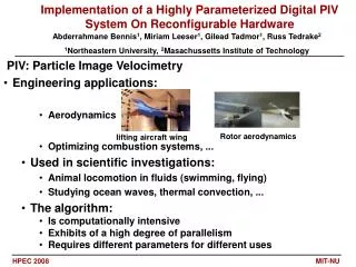
Particle Image Velocimetry • Used to measure the velocity of a flow field cross section • Laser creates a light sheet through the flow • Cameras take quick series of images • Correlation yields velocities • Multiple cross sections create a 3D map of the flow field Image courtesy of LaVision
The Project Symphony • Measure flow from a jet engine • Two sides to project • Mechanical • Digital • Focus on the digital side
Requirements • Control: • 3 high resolution cameras • 2 lasers • One 2D traverse • Retrieve images from cameras • 10 images per second • Use Qinetiq’s Noise Test Facility
Problems • Obvious issues • Hostile conditions • Less obvious issues • Large amount of data • High acquisition rate • Limited hardware
Problems Hostile conditions • Vibrations • High frequency and low frequency • Very hot • Around 850K in the centre • Controlled from ~400m away • No one is allowed in the test chamber during experiments
Problems Large amount of data • 192GiB per run • 2048 × 2048 pixel 8 bit frames • 1000 double frames in each position • 48 positions • Cannot use conventional hard drives close to cameras • Too much vibration • Currently large solid state drives (SSDs) are expensive • £1150 for a 512GB SSD • Reasonable prices for 32-64GB SSDs
Problems High acquisition rate • Capturing frames at 10Hz • 40MiB/s • Maximum speed of Gigabit Ethernet is 125 MB/s • Overheads reduce this to around 80MB/s • Too slow to transfer multiple images simultaneously • 10 Gigabit exists but is extremely expensive • Hard drive speeds around 70 MB/s • Again too slow to write multiple images simultaneously
Problems Limited hardware • PCO cameras • Proprietary cables ~4m long • Interfaces with PCI card • Hard drives • Slow • Vulnerable to vibration • Lasers • Need local triggering
Network Design Driving the devices • Trigger Box • Used to synchronise the cameras and lasers • Accurate to the nanosecond scale • Solid State Based Computers • Are not affected by vibrations • Cannot be far from cameras due to cable length • Do not have capacity to store images long term • Also used to control traverse
Network Design Storing the data • Backup Servers • RAID5 based • Redundancy • Good usage of disk space • ~3.5TB per server • Placed at ground level away from serious vibration • Dedicated Gigabit Ethernet for each server • Only enough bandwidth for one camera’s images each
Network Design Managing the Network • Ethernet to each computer • Separate to data transfer lines • Control Terminal • Placed in control room • Remote desktop used to access other computers • Also used for monitoring other computers
Results • Working well with single camera, SSD computer, and backup server • Waiting for shipment of components to build full system