Download
1 / 18
190 likes | 195 Views
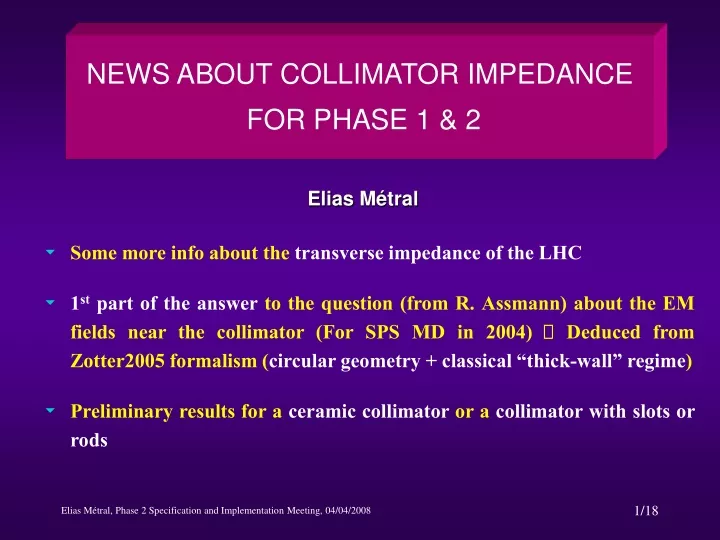
NEWS ABOUT COLLIMATOR IMPEDANCE FOR PHASE 1 & 2. Elias Métral. Some more info about the transverse impedance of the LHC

E N D
NEWS ABOUT COLLIMATOR IMPEDANCE FOR PHASE 1 & 2 Elias Métral • Some more info about the transverse impedance of the LHC • 1st part of the answer to the question (from R. Assmann) about the EM fields near the collimator (For SPS MD in 2004) Deduced from Zotter2005 formalism (circular geometry + classical “thick-wall” regime) • Preliminary results for a ceramic collimator or a collimator with slots or rods
ZOTTER2005’S THEORY FOR 1 GRAPHITE COLLIMATOR 3) “High-frequency” regime Not relevant for LHC! 1) “Inductive-bypass” regime 2) Classical “thick-wall” regime Interesting frequency range for LHC From few kHz to few GHz
SIMPLEST FORMULA FOR THE LHC COLLIMATOR TRANSVERSE IMPEDANCE (round case) (1/2) Valid for any relatively good conductor with r real and r = 1 with Modified Bessel function There are Yokoya’s factors to go from round to flat (2 / 12 and 2 / 24 ) Classical “thick-wall” regime
SIMPLEST FORMULA FOR THE LHC COLLIMATOR TRANSVERSE IMPEDANCE (round case) (2/2) The maximum of the real part is reached when It is a broad maximum This scaling was also found analytically using the approximated model of L. Vos (as said in the LHC Design Report, p. 100) N.A.:
ZOOM (between 8 kHz and 20 MHz) OF THE LHC TRANSVERSE IMPEDANCE AT TOP ENERGY (AFTER THE SQUEEZE) • The value of the real part of the impedance at 8 kHz (1st unstable betatron line) is ~ 141 M/m • The value of the real part of the impedance at 20 MHz (frequency limit of the transverse damper) is ~ 55 M/m • The ratio between the two values is only ~ 2.6 (it would have been 50 in the case of the classical resistive-wall theory!) • And, as the gain of the power amplifier rolls off rapidly when approaching 20 MHz, there might be some problems there…
SOURCE CHARGE DENSITY USED FOR THE COMPUTATIONS • A macro-particle of charge is assumed to move along the pipe (in the s - direction) with an offset in the direction and with velocity A cos m beam generates EM fields in cos m and sin m Different multipoles are decoupled (consequence of the axial symmetry) The charge density can be written where is the mth multipole moment • The cylindrical coordinate system is used • Numerical values are given for the 2004 SPS experiment
REMINDER: Perfectly Conducting wall (1/3) m = 0 m = 1 Used to compute the longitudinal impedance Used to compute the transverse impedance
REMINDER: Perfectly Conducting wall (2/3) Force on a particle with charge q m = 0 m = 1
REMINDER: Perfectly Conducting wall (3/3) m = 0 m = 1 For L = 2 R For L = 2 R Behind the bunch
CASE OF A RESISTIVE OBJECT (1/4) m = 0 m = 1 z > 0 is ahead of the beam and z < 0 is behind the beam Different from Chao page 54 (see next slide)!
CASE OF A RESISTIVE OBJECT (2/4) I have (at the moment…) for m = 1 Chao finds the same result for r = band = 0 r = 1 for Chao Chao has (r2 – b2) instead of r2 Chao finds a result 2 times bigger Chao has (r2 + b2) instead of r2
CASE OF A RESISTIVE OBJECT (3/4) m = 0 m = 1
CASE OF A RESISTIVE OBJECT (4/4) m = 0 m = 1
PRELIMINARY ANALYTICAL COMPUTATIONS OF THE TRANSVERSE IMPEDANCE OF A CERAMIC COLLIMATOR (1/2) Scan in resistivity from 10-6 to 1020 m and Many thanks to Fritz and Alexej for many interesting discussions!
PRELIMINARY ANALYTICAL COMPUTATIONS OF THE TRANSVERSE IMPEDANCE OF A CERAMIC COLLIMATOR (2/2) 1 layer of thickness 2.5 cm and then Perfect Conductor 1 layer of infinite thickness 1 layer of thickness 2.5 cm and then Perfect Conductor + Lossy dielectric
PRELIMINARY SIMULATIONS OF THE TRANSVERSE IMPEDANCE OF A CERAMIC COLLIMATOR BY TOM KROYER Typo “below” Typo “above” In conclusion: Only preliminary results for the moment!!! We still need to carefully check them!
Full Cu Slots Rods NEWS ABOUT COLLIMATOR WITH SLOTS & RODS (1/2) Current density at 10 kHz Width = 1 mm Depth = 5 mm 22 mm2 Length = 5 mm
NEWS ABOUT COLLIMATOR WITH SLOTS & RODS (2/2) • Measurements were also started by Fritz, Benoit and Federico More news soon…