Download
1 / 18
180 likes | 312 Views
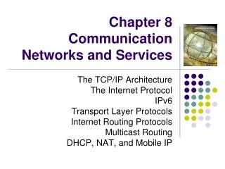
Chapter 1 Communication Networks and Services. Chapter Figures. 1.0E+14. 1.0E+12. 1.0E+10. 1.0E+08. 1.0E+06. 1.0E+04. 1.0E+02. 1.0E+00. 1850. 1875. 1900. 1925. 1950. 1975. 2000. DWDM. SONET OC-48. T-4 carrier. T-1 carrier. Transmission rate (bits/second). Baudot multiplex.

E N D
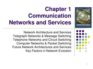
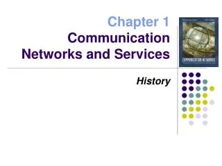
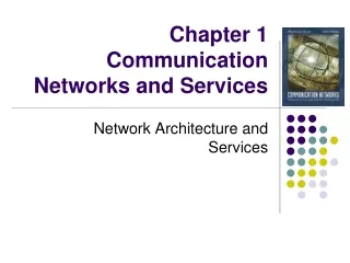
Chapter 1 Communication Networks and Services Chapter Figures
1.0E+14 1.0E+12 1.0E+10 1.0E+08 1.0E+06 1.0E+04 1.0E+02 1.0E+00 1850 1875 1900 1925 1950 1975 2000 DWDM SONET OC-48 T-4 carrier T-1 carrier Transmission rate (bits/second) Baudot multiplex Printing telegraph Figure 1.1 Communication Networks
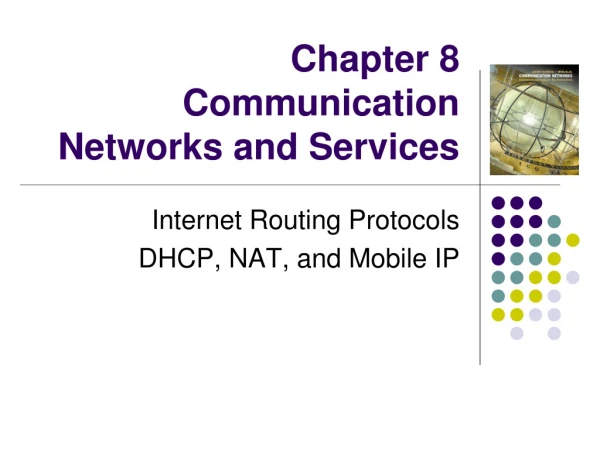
Figure 1.2 Communication Networks
User 1 (a) User N … (b) (c) User 2 Figure 1.3 Communication Networks
Toll Tandem Tandem CO CO CO CO CO CO = central office Figure 1.4 Communication Networks
Telephone network Telephone network Telephone network Telephone network Telephone network Telephone network 1. The caller picks up the phone triggering the flow of current in wires that connect to the telephone office. 1. 2. The current is detected, and a dial tone is transmitted by the telephone office to indicate that it is ready to receive the destination number. 2. Connection setup 3. The caller sends this number by pushing the keys on the telephone set. Each key generates a pair of tones that specify a number. (In the older phone sets, the user dials a number that in turn generates a corresponding number of pulses.) 3. 4. The equipment in the telephone office then uses the telephone network to attempt a con-nection. If the destination telephone is busy, then a busy tone is returned to the caller; otherwise ringing signals are sent to both the originating and destination telephones. The ringing signals are discontinued when the destination phone is picked up and communication can then proceed. 4. Information transfer 5. 5. The voice signals travel in both directions. Connection release 6. Either user terminates the call by putting down a receiver. 6. Figure 1.5 Communication Networks
Caller Dials 411 System replies “What city”? Caller replies “Springfield” System replies “What name?” Caller replies “Simpson” System replies “Thank you, please hold” Caller waits “Do you have a first name or street?” Operator replies Caller replies “Evergreen Terrace” Operator replies “Thank you, please hold” Caller waits System replies with number Caller dials Figure 1.6 Communication Networks
T C . . . T T . . . C T T Telephone network Modem pool Modem T (a) (b) C = computer T = terminal Figure 1.7 Communication Networks
Poll to terminal C Response from terminal T T T T Figure 1.8 Communication Networks
CRC Information Address T . . . Host Mux T Address Information CRC T Figure 1.9 Communication Networks
Host . . . . . . San Francisco New York City T . . . T . . . Chicago Atlanta T Figure 1.10 Communication Networks
H H H H PS PS PS PS H PS = packet switch H = host Figure 1.11 Communication Networks
AMES UTAH BOULDER GWC CASE MCCLELLAN RADC ILL CARN LINC USC AMES MIT MITRE UCSB STAN SCD ETAC UCLA RAND TINKER BBN HARV NBS Figure 1.12 Communication Networks
(b) (a) Transceivers Figure 1.13 Communication Networks
Net 3 H H H H Net 1 G G G G G G Net 5 Net 2 Net 4 G = gateway H = host Figure 1.14 Communication Networks
Technology Standards Market Regulation Figure 1.15 Communication Networks
Capability Capability Third class of invention Second class of invention Initial class of invention Time Time (b) (a) Figure 1.16 Communication Networks
P4 Pentium III Pentium II Transistor count Pentium Pro Pentium 486 DX Intel DX2 80286 8086 8080 4004 1972 1982 1992 2002 Figure 1.17 Communication Networks