Download
1 / 46
460 likes | 595 Views
The TCP/IP Architecture & The Internet Protocol. Chapter 8 Communication Networks and Services. The TCP/IP Architecture. Chapter 8 Communication Networks and Services. Why Internetworking?. To build a “network of networks” or internet

E N D
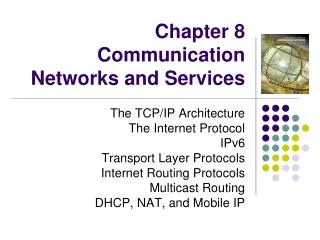
The TCP/IP Architecture & The Internet Protocol Chapter 8 Communication Networks and Services
The TCP/IP Architecture Chapter 8 Communication Networks and Services
Why Internetworking? To build a “network of networks” or internet operating over multiple, coexisting, different network technologies providing ubiquitous connectivity through IP packet transfer achieving huge economies of scale H H Net 3 Net 5 Net 1 G Net 5 G G G Net 5 Net 5 G G H Net 2 Net 4 Net 5 Net 5 H
Why Internetworking? To provide universal communication services independent of underlying network technologies providing common interface to user applications H Reliable Stream Service H Net 3 Net 5 Net 1 G Net 5 G G G Net 5 Net 5 G G H Net 2 Net 4 Net 5 Net 5 H User Datagram Service
Why Internetworking? To provide distributed applications Any application designed to operate based on Internet communication services immediately operates across the entire Internet Rapid deployment of new applications Email, WWW, Peer-to-peer Applications independent of network technology New networks can be introduced below Old network technologies can be retired
Internet Protocol Approach Router Host A Router Transport Layer Internet Layer Transport Layer Internet Layer Internet Layer Network Interface Internet Layer Net 1 Net 5 Network Interface Router Network Interface Network Interface Internet Layer Net 4 Net 5 Network Interface Net 3 Net 5 Net 2 Net 5 • IP packets transfer information across Internet Host A IP → router→ router…→ router→ Host B IP • IP layer in each router determines next hop (router) • Network interfaces transfer IP packets across networks Host B
SMTP HTTP DNS RTP IP Network Interface 3 Network Interface 1 Network Interface 2 TCP/IP Protocol Suite Distributed applications User datagram service Reliable stream service TCP UDP Best-effort connectionless packet transfer (ICMP, ARP) Diverse network technologies
Internet Names & Addresses Internet Names Each host has a unique name Independent of physical location Facilitate memorization by humans Domain Name Organization under single administrative unit Host Name Name given to host computer User Name Name assigned to user leongarcia@comm.utoronto.ca Internet Addresses Each host has globally unique logical 32 bit IP address Separate address for each physical connection to a network Routing decision is done based on destination IP address IP address has two parts: netid and hostid netid unique netid facilitates routing Dotted Decimal Notation: int1.int2.int3.int4 (intj = jth octet) 128.100.10.13 DNS resolves IP name to IP address
Physical Addresses LANs (and other networks) assign physical addresses to the physical attachment to the network The network uses its own address to transfer packets or frames to the appropriate destination IP address needs to be resolved to physical address at each IP network interface Example: Ethernet uses 48-bit addresses Each Ethernet network interface card (NIC) has globally unique Medium Access Control (MAC) or physical address First 24 bits identify NIC manufacturer; second 24 bits are serial number 00:90:27:96:68:07 12 hex numbers Intel
Encapsulation HTTP Request TCP Header contains source & destination port numbers TCP header HTTP Request IP Header contains source and destination IP addresses; transport protocol type IP header TCP header HTTP Request Ethernet Header contains source & destination MAC addresses; network protocol type Ethernet header TCP header IP header FCS HTTP Request
The Internet Protocol Chapter 8 Communication Networks and Services
Internet Protocol Provides best effort, connectionless packet delivery motivated by need to keep routers simple and by adaptibility to failure of network elements packets may be lost, out of order, or even duplicated higher layer protocols must deal with these, if necessary RFCs 791, 950, 919, 922, and 2474. IP is part of Internet STD number 5, which also includes: Internet Control Message Protocol (ICMP), RFC 792 Internet Group Management Protocol (IGMP), RFC 1112
IP Packet Header 0 4 8 16 19 24 31 Version IHL Type of Service Total Length Identification Flags Fragment Offset Time to Live Protocol Header Checksum Source IP Address Destination IP Address Options Padding • Minimum 20 bytes • Up to 40 bytes in options fields
IP Packet Header 0 4 8 16 19 24 31 Version IHL Type of Service Total Length Identification Flags Fragment Offset Time to Live Protocol Header Checksum Source IP Address Destination IP Address Options Padding Version: current IP version is 4. Internet header length (IHL): length of the header in 32-bit words. Type of service (TOS): traditionally priority of packet at each router. Recent Differentiated Services redefines TOS field to include other services besides best effort.
IP Packet Header 0 4 8 16 19 24 31 Version IHL Type of Service Total Length Identification Flags Fragment Offset Time to Live Protocol Header Checksum Source IP Address Destination IP Address Options Padding Total length: number of bytes of the IP packet including header and data, maximum length is 65535 bytes. Identification, Flags, and Fragment Offset: used for fragmentation and reassembly (More on this shortly).
IP Packet Header 0 4 8 16 19 24 31 Version IHL Type of Service Total Length Identification Flags Fragment Offset Time to Live Protocol Header Checksum Source IP Address Destination IP Address Options Padding • Time to live (TTL): number of hops packet is allowed to traverse in the network. • Each router along the path to the destination decrements this value by one. • If the value reaches zero before the packet reaches the destination, the router discards the packet and sends an error message back to the source.
IP Packet Header 0 4 8 16 19 24 31 Version IHL Type of Service Total Length Identification Flags Fragment Offset Time to Live Protocol Header Checksum Source IP Address Destination IP Address Options Padding Protocol: specifies upper-layer protocol that is to receive IP data at the destination. Examples include TCP (protocol = 6), UDP (protocol = 17), and ICMP (protocol = 1). Header checksum: verifies the integrity of the IP header. Source IP address and destination IP address: contain the addresses of the source and destination hosts.
IP Packet Header 0 4 8 16 19 24 31 Version IHL Type of Service Total Length Identification Flags Fragment Offset Time to Live Protocol Header Checksum Source IP Address Destination IP Address Options Padding Options: Variable length field, allows packet to request special features such as security level, route to be taken by the packet, and timestamp at each router. Detailed descriptions of these options can be found in [RFC 791]. Padding: This field is used to make the header a multiple of 32-bit words.
Header Checksum IP header uses check bits to detect errors in the header A checksum is calculated for header contents Checksum recalculated at every router, so algorithm selected for ease of implementation in software Let header consist of L, 16-bit words, b0, b1, b2, ..., bL-1 The algorithm appends a 16-bit checksumbL
Checksum Calculation The checksum bL is calculated as follows: Treating each 16-bit word as an integer, find x = b0 + b1 + b2+ ...+ bL-1 modulo 215-1 The checksum is then given by: bL = - x modulo 215-1 This is the 16-bit 1’s complement sum of the b’s If checksum is 0, use all 1’s representation (all zeros reserved to indicate checksum was not calculated) Thus, the headers must satisfy the followingpattern: 0 = b0 + b1 + b2+ ...+ bL-1 + bL modulo 215-1
IP Header Processing Compute header checksum for correctness and check that fields in header (e.g. version and total length) contain valid values Consult routing table to determine next hop Change fields that require updating (TTL, header checksum)
IP Addressing RFC 1166 Each host on Internet has unique 32 bit IP address Each address has two parts: netid and hostid netid unique & administered by American Registry for Internet Numbers (ARIN) Reseaux IP Europeens (RIPE) Asia Pacific Network Information Centre (APNIC) Facilitates routing A separate address is required for each physical connection of a host to a network; “multi-homed” hosts Dotted-Decimal Notation: int1.int2.int3.int4 where intj = integer value of jth octet IP address of 10000000 10000111 01000100 00000101 is 128.135.68.5 in dotted-decimal notation
Classful Addresses • 126 networks with up to 16 million hosts • 16,382 networks with up to 64,000 hosts • 2 million networks with up to 254 hosts Class A 7 bits 24 bits hostid netid 0 1.0.0.0 to 127.255.255.255 Class B 14 bits 16 bits hostid 0 netid 1 128.0.0.0 to 191.255.255.255 Class C 21 bits 8 bits 0 netid hostid 1 1 192.0.0.0 to 223.255.255.255
Up to 250 million multicast groups at the same time Permanent group addresses All systems in LAN; All routers in LAN; All OSPF routers on LAN; All designated OSPF routers on a LAN, etc. Temporary groups addresses created as needed Special multicast routers Class D 28 bits 0 1 1 1 multicast address 224.0.0.0 to 239.255.255.255
Reserved Host IDs (all 0s & 1s) Broadcast address has hostid set to all 1s Internet address used to refer to network has hostid set to all 0s this host (used when booting up) 0 0 0 0 0 0 a host in this network 0 0 0 host broadcast on local network 1 1 1 1 1 1 broadcast on distant network 1 1 1 1 1 1 netid 1
Private IP Addresses Specific ranges of IP addresses set aside for use in private networks (RFC 1918) Use restricted to private internets; routers in public Internet discard packets with these addresses Range 1: 10.0.0.0 to 10.255.255.255 Range 2: 172.16.0.0 to 172.31.255.255 Range 3: 192.168.0.0 to 192.168.255.255 Network Address Translation (NAT) used to convert between private & global IP addresses
Example of IP Addressing H H R H H H 128.140.5.40 128.135.40.1 Interface Address is 128.135.10.2 Interface Address is 128.140.5.35 Network 128.135.0.0 Network 128.140.0.0 Subnet mask = ? 128.135.10.20 128.135.10.21 128.140.5.36 Address with host ID=all 0s refers to the network Address with host ID=all 1s refers to a broadcast packet R = router H = host
Subnet Addressing • Subnet addressing introduces another hierarchical level • Transparent to remote networks • Simplifies management of multiplicity of LANs • Masking used to find subnet number
Subnetting Example Organization has Class B address (16 host ID bits) with network ID: 150.100.0.0 Create subnets with up to 100 hosts each 7 bits sufficient for each subnet 16-7=9 bits for subnet ID Apply subnet mask to IP addresses to find corresponding subnet Example: Find subnet for 150.100.12.176 IP add = 10010110 01100100 00001100 10110000 Mask = 11111111 11111111 11111111 10000000 AND = 10010110 01100100 00001100 10000000 Subnet = 150.100.12.128 Subnet address used by routers within organization
Subnet Example H1 H2 150.100.12.154 150.100.12.176 150.100.12.128 150.100.12.129 255.255.255.128=subnet mask 150.100.0.1 R1 To the rest of H3 H4 150.100.12.4 the Internet 150.100.12.55 150.100.12.24 150.100.12.0 150.100.12.1 R2 H5 150.100.15.54 150.100.15.11 150.100.15.0
Routing with Subnetworks IP layer in hosts and routers maintain a routing table Originating host: To send an IP packet, consult routing table If destination host is in same network, send packet directly using appropriate network interface Otherwise, send packet indirectly; typically, routing table indicates a default router Router: Examine IP destination address in arriving packet If dest IP address not own, router consults routing table to determine next-hop and associated network interface & forwards packet
Routing Table Each row in routing table contains: Destination IP address IP address of next-hop router Physical address Statistics information Flags H=1 (0) indicates route is to a host (network) G=1 (0) indicates route is to a router (directly connected destination) Routing table search order & action Complete destination address; send as per next-hop & G flag Destination network ID; send as per next-hop & G flag Default router entry; send as per next-hop Declare packet undeliverable; send ICMP “host unreachable error” packet to originating host
Example: Host H5 sends packet to host H2 H1 H2 150.100.12.154 150.100.12.176 150.100.12.128 150.100.12.129 150.100.0.1 R1 To the rest of H3 H4 150.100.12.4 the Internet 150.100.12.55 150.100.12.24 150.100.12.0 150.100.12.1 R2 H5 150.100.15.54 150.100.15.11 150.100.15.0 Destination Next-Hop Flags Net I/F 127.0.0.1 127.0.0.1 H lo0 default 150.100.15.54 G emd0 150.100.15.0 150.100.15.11 emd0 150.100.12.176 Routing Table at H5
Example: Host H5 sends packet to host H2 H1 H2 150.100.12.154 150.100.12.176 150.100.12.128 150.100.12.129 150.100.0.1 R1 To the rest of H3 H4 150.100.12.4 the Internet 150.100.12.55 150.100.12.24 150.100.12.0 150.100.12.1 150.100.12.176 R2 H5 150.100.15.54 150.100.15.11 Destination Next-Hop Flags Net I/F 127.0.0.1 127.0.0.1 H lo0 default 150.100.12.4 G emd0 150.100.15.0 150.100.15.54 emd1 150.100.12.0 150.100.12.1 emd0 150.100.15.0 Routing Table at R2
Example: Host H5 sends packet to host H2 H1 H2 150.100.12.154 150.100.12.176 150.100.12.128 150.100.12.176 150.100.12.129 150.100.0.1 R1 To the rest of H3 H4 150.100.12.4 the Internet 150.100.12.55 150.100.12.24 150.100.12.0 150.100.12.1 R2 H5 150.100.15.54 150.100.15.11 Destination Next-Hop Flags Net I/F 127.0.0.1 127.0.0.1 H lo0 150.100.12.176 150.100.12.176 emd0 150.100.12.0 150.100.12.4 emd1 150.100.15.0 150.100.12.1 G emd1 150.100.15.0 Routing Table at R1
Subnet Example H1 H2 10.192.1.4 10.192.1.6 10.192.0.0 10.192.2.9 255.255.0.0=subnet mask 10.101.0.1 R1 To the rest of H3 H4 10.119.2.4 the Internet 10.119.1.55 10.119.2.2 10.119.0.0 10.119.12.1 R2 H5 10.140.5.54 10.140.5.11 Gateway for each host:??? H5=10.140.5.54 H4=H3=10.119.2.4 H1=H2=10.192.2.9 10.140.0.0
In the 1990, two problems became apparent IP addresses were being exhausted IP routing tables were growing very large IP Address Exhaustion Class A, B, and C address structure inefficient Class B too large for most organizations, but future proof Class C too small Rate of class B allocation implied exhaustion by 1994 IP routing table size Growth in number of networks in Internet reflected in # of table entries From 1991 to 1995, routing tables doubled in size every 10 months Stress on router processing power and memory allocation Short-term solution: Classless Interdomain Routing (CIDR), RFC 1518 New allocation policy (RFC 2050) Private IP Addresses set aside for intranets Long-term solution: IPv6 with much bigger address space IP Address Problems
Class A & B assigned only for clearly demonstrated need Consecutive blocks of class C assigned (up to 64 blocks) All IP addresses in the range have a common prefix, and every address with that prefix is within the range Arbitrary prefix length for network ID improves efficiency Lower half of class C space assigned to regional authorities More hierarchical allocation of addresses Service provider to customer New Address Allocation Policy Address Requirement Address Allocation < 256 1 Class C 256<,<512 2 Class C 512<,<1024 4 Class C 1024<,<2048 8 Class C 2048<,<4096 16 Class C 4096<,<8192 32 Class C 8192<,<16384 64 Class C
Supernetting Summarize a contiguous group of class C (or B??) addresses using variable-length mask Example: 150.158.16.0/20 IP Address (150.158.16.0) & mask length (20) IP add = 10010110 10011110 00010000 00000000 Mask = 11111111 1111111111110000 00000000 Contains 16 Class C (or B??) blocks: From 10010110 1001111000010000 00000000 i.e. 150.158.16.0 Up to 10010110 1001111000011111 00000000 i.e. 150.158.31.0
Classless Inter-Domain Routing CIDR deals with Routing Table Explosion Problem Networks represented by prefix and mask Pre-CIDR: Network with range of 16 contiguous class C blocks requires 16 entries Post-CIDR: Network with range of 16 contiguous class C blocks requires 1 entry Solution: Route according to prefix of address, not class Routing table entry has <IP address, network mask> Example: 192.32.136.0/21 11000000 00100000 10001000 00000001 min address 11111111 11111111 11111--- -------- mask 11000000 00100000 10001--- -------- IP prefix 11000000 00100000 10001111 11111110max address 11111111 11111111 11111--- -------- mask 11000000 00100000 10001--- -------- same IP prefix
Hierarchical Routing & Table Efficiency 0100 0101 0110 0111 0000 0001 0010 0011 R2 R1 1100 1101 1110 1111 1000 1001 1010 1011 00 1 01 3 10 2 11 3 00 3 01 4 10 3 11 5 0001 0100 1011 1110 0000 0111 1010 1101 R2 R1 0011 0101 1000 1111 0011 0110 1001 1100 0001 4 0100 4 1011 4… … 0000 1 0111 1 1010 1… … (a) NET_4 NET_1 1 4 3 5 2 NET_5 NET_2 (b) 1 4 3 5 2
CIDR Allocation Principles (RFC 1518-1520) IP address assignment reflects physical topology of network Network topology follows continental/national boundaries IP addresses should be assigned on this basis Transit routing domains (TRDs) have unique IP prefix carry traffic between routing domains interconnected non-hierarchically, cross national boundaries Most routing domains single-homed: attached to a single TRD Such domains assigned addresses with TRD's IP prefix All of the addresses attached to a TRD aggregated into 1table entry Implementation primarily through BGPv4 (RFC 1520)
Longest Prefix Match CIDR impacts routing & forwarding Routing tables and routing protocols must carry IP address and mask Multiple entries may match a given IP destination address Example: Routing table may contain 205.100.0.0/22 which corresponds to a given supernet 205.100.0.0/20 which results from aggregation of a larger number of destinations into a supernet Packet must be routed using the more specific route, that is, the longest prefix match Several fast longest-prefix matching algorithms are available
Address Resolution Protocol Although IP address identifies a host, the packet is physically delivered by an underlying network (e.g., Ethernet) which uses its own physical address (MAC address in Ethernet). How to map an IP address to a physical address? H1 H2 H3 H4 150.100.76.22 150.100.76.23 150.100.76.20 150.100.76.21 ARP request (what is the MAC address of 150.100.76.22?) H1 H2 H3 H4 ARP response (my MAC address is 08:00:5a:3b:94) H1 wants to learn physical address of H3 -> broadcasts an ARP request Every host receives the request, but only H3 reply with its physical address