Download
1 / 150
1.55k likes | 1.62k Views
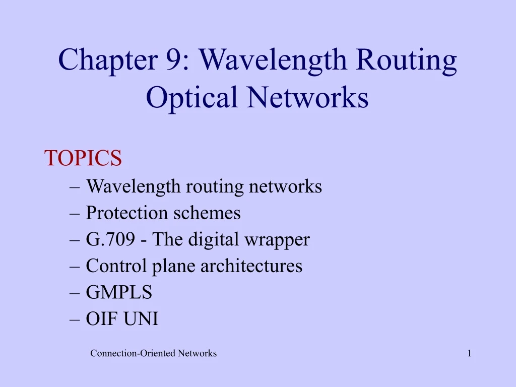
Chapter 9: Wavelength Routing Optical Networks. TOPICS Wavelength routing networks Protection schemes G.709 - The digital wrapper Control plane architectures GMPLS OIF UNI. A wavelength routing network.

E N D
Chapter 9: Wavelength Routing Optical Networks TOPICS • Wavelength routing networks • Protection schemes • G.709 - The digital wrapper • Control plane architectures • GMPLS • OIF UNI Connection-Oriented Networks
A wavelength routing network This is an optical network that consists of OXCs interconnected by WDM fibers, with each fiber consisting of W wavelengths Switchfabric … … Output WDM fibers Input WDM fibers … … … … DCS . . . Connection-Oriented Networks
OXC functionality • It switches optically all the incoming wavelengths of the input fibers to the outgoing wavelengths of the output fibers. • For instance, it can switch the optical signal on incoming wavelength i of input fiber k to the outgoing wavelength i of output fiber m. Connection-Oriented Networks
Converters: If it is equipped with converters, it can also switch the optical signal of the incoming wavelength i of input fiber k to another outgoing wavelength j of the output fiber m. This happens when the wavelength i of the output fiber m is in use. Connection-Oriented Networks
Optical add/drop multiplexer (OADM): An OXC can also be used as an OADM. That is, it can terminate the optical signal of a number of incoming wavelengths and insert new optical signals on the same wavelengths in an output port. The remaining incoming wavelengths are switched through as described above. Connection-Oriented Networks
Transparent and Opaque Switches Transparent switch: The incoming wavelengths are switched to the output fibers optically, without having to convert them to the electrical domain. Opaque switch: The input optical signals are converted to electrical signals, from where the packets are extracted. Packets are switched using a packet switch, and then they are transmitted out of the switch in the optical domain. Connection-Oriented Networks
Lightpaths • Wavelength routing networks are circuit-switched networks. • In order for a user to send data to a another user, a connection has to be first setup. • This connection is a circuit-switched connection and it is established by allocating a wavelength on each hop along the connection’s path Connection-Oriented Networks
An example of a lightpath Router A OXC 1 OXC 2 OXC 3 Router B 1W 1W 1W 1W A three-node wavelength routing network Router A Router B OXC 1 OXC 2 OXC 3 1 1 1 1 A lightpath between routers A and B Connection-Oriented Networks
The wavelength continuity constraint • When establishing a lightpath over a wavelength routing network, the same wavelength has to be used on every hop along the path. • If the required wavelength is not available at the outgoing fiber of an OXC through which the lightpath has to be routed, then the establishment of the lightpath is blocked, and a notification message is sent back to the user. Connection-Oriented Networks
Converters • In order to decrease the probability that a lightpath is blocked, the OXC can be equipped with converters. • A converter can transform the optical signal transmitted over a wavelength to another wavelength. Connection-Oriented Networks
In an OXC, for each output fiber with W wavelengths, there may be c converters, where 0 ≤ c ≤W. • No conversion: c=0 • Partialconversion: 0 < c <W • Full conversion: c=W A converter can only transform a signal on a wavelength to another wavelength which is within a few nm from wavelength . Connection-Oriented Networks
λ1 λ1 λ1 λ1 λ2 λ1 WL utilization improvement through WL conversion • Without conversion • 2 optical connections from A to C, and from F to C • Assuming 2 WLs (lambda1, lambda2) per fiber and F is connected to B C D A B Connection-Oriented Networks F E
λ2 λ1 λ1 λ1 λ2 WL utilization improvement through WL conversion • With conversion • 2 optical connections from A to C, and from F to C • Assuming 2 WLs (lambda1, lambda2) per fiber and F is connected to B C D B A Connection-Oriented Networks F E
An example of different lightpaths Router D E O 2 1 Lightpaths A -> C: 1 B -> D:1 and 2 C -> D:3and 1 OXCs 1 and 2: no converters OXC 3 has converters 1 3 OXC 3 OXC 1 OXC 2 Router A 3 Router C 1 1 1 E O 1 O E O E Router B Connection-Oriented Networks
Traffic grooming • A lightpath is exclusively used by a single client. • Often the bandwidth a client requires is significantly less than the wavelength’s bandwidth. This means that part of the lightpath’s bandwidth is unused. Also, the user pays for more bandwidth than required. • Traffic grooming permits mane user to share the same lightpath. Connection-Oriented Networks
Sub-rate units • The bandwidth of a lightpath is divided into sub-rate units so that it can carry traffic streams transmitted at lower rates. • For instance a 2.5 Gbps (OC-48) bandwidth can be available in sub-rate units of 50 Mbps (OC-1) • A client can request one or more of these sub-rate units. This improves wavelength utilization and lowers user’s costs. Connection-Oriented Networks
An example of traffic grooming OXC 3 OXC 2 • Established lightpaths: • OXC 1 to OXC 3 • OXC 3 to OXC 4 • Transmission rate: 2.488 Gbps (OC-48/STM-16) • 16 sub-rate units of 155 Mbps (OC3/STM-1) 1 1 OXC 1 OXC 4 2 2 OXC 6 OXC 5 Connection-Oriented Networks
A user attached to OXC 1 that wants to transmit data to a user attached to OXC 3, can request any integer number of OC-3/STM-1 sub-rate units up to a total of 16. • Additional lightpaths can be established between OXCs 1 and 3, if the traffic between these two OXCs exceeds 2.488 Gbps. Connection-Oriented Networks
Traversing more than one lightpath: • Let us consider a user attached to OXC 1 who requests a connection to a user attached to OXC 4 for four sub-rate units. • In this case, a new lightpath has to be established between OXCs 1 and 4, say, over OXCs 6 and 5. Connection-Oriented Networks
Alternatively, the connection can be routed through the two lightpaths (OXC 1 -> OXC 3 and OXC 3 -> OXC 4). • Provided that there is free capacity on each lightpath and OXC 3 is equipped with a SONET/SDH DCS which permits it to extract the data stream from the incoming SONET/SDH frames on the first lightpath and place it into the SONET/SDH frames of the second lightpath. Connection-Oriented Networks
Protection schemes Optical networks will be used by telecommunications companies and other network providers, which typically require a carrier grade reliability. That is, the network has to be available 99.999% of the time, which translates to an average downtime for the network of 6 minutes per year! Connection-Oriented Networks
Types of failures: • Link failures are very common and they occur when a fiber cable is accidentally cut. • A link can also fail if an amplifier that boosts the multiplexed signal of all the wavelengths on the fiber fails. • An individual wavelength within a fiber may also fail if its transmitter or receiver fails. • Finally, an OXC can fail, but this is quite rare due to built-in redundancies. Connection-Oriented Networks
Path and link protection Protection can be performed at the level of an individual lightpath or at the level of a single fiber. • Path protection denotes schemes for the restoration of a lightpath, and • Linkprotection denotes schemes for the restoration of a single fiber, whereby all the wavelengths are restored simultaneously. Connection-Oriented Networks
Point-to-point links • The simplest optical network is a point-to-point WDM link that connects two nodes. • Link protection can be done in a • dedicated 1+1 manner, or in a • non-dedicated1:1 or 1:N manner Connection-Oriented Networks
Dedicated 1+1 scheme: • the signal is transmitted simultaneously over two separate fibers which are preferably diversely routed. • The receiver monitors the quality of the two signals and selects the best of the two. • If one fiber fails, then the receiver continues to receive data on the other fiber. Connection-Oriented Networks
1:1 scheme: • There are still two diversely routed fibers, a working fiber and a protection fiber. • The signal is transmitted over the working fiber, and if this fiber fails, the source and destination switch to the protection fiber. • Shared 1:N scheme: • This is a generalization of the 1:1 scheme, where N working fibers are protected by a single protection fiber. (Only one working fiber can be protected at any time. ) Connection-Oriented Networks
WDM optical rings • WDM optical rings can be seen as an extension of the SONET/SDH rings in the WDM domain. • Many different WDM ring architectures have been proposed. We examine the following rings: • optical unidirectional path sharing ring (OUPSR), • two-fiber optical bidirectional link sharing ring (2F-OBLSR) • four-fiber optical bidirectional link sharing ring (4F-OBLSR). Connection-Oriented Networks
An optical unidirectional path sharing ring (OUPSR) A Protection fiber Working fiber B Connection-Oriented Networks
Features • It consists of a working and a protection ring transmitting in opposite directions • It used as a metro edge ring, and it connects a small number of nodes, such as access networks and customer premises, to a hub node, which is attached to a metro core ring. • The traffic transmitted on the ring is static and it exhibits hub behavior. That is, it is directed from the nodes to the hub and from the hub to the nodes. Static lightpaths are used. Connection-Oriented Networks
Features • Transmission is unidirectional. • The 1+1 protection scheme is used to implement a simple path protection scheme. That is, a lightpath, is split at the source node and it is transmitted over the working and protection ring. • The destination selects the best signal. Connection-Oriented Networks
2F-OBLSR and 4F -OBLSR • The two-fiber and four-fiber optical bidirectional link shared rings are used in the metro core where the traffic patterns dynamically change. • A signaling protocol is used to establish and tear down lightpaths. • Protection schemes are implemented using a real-time distributed protection signaling protocol known as the optical automatic protection switching (optical APS) Connection-Oriented Networks
The two-fiber optical bidirectional link shared ring • It utilizes two rings transmitting in opposite direction as in the OUPSR. • The wavelengths is each fiber are grouped into two sets: one for working wavelengths and one for protection wavelengths. • If a fiber fails, the traffic is re-routed onto the protection wavelengths of the other fiber. Connection-Oriented Networks
The four-fiber optical bidirectional link shared ring Node 2 Node 1 Ring switching A Span switching Working fibers Protection fibers B Node 3 Node 4 Connection-Oriented Networks
Features • It utilizes two working fibers and two protection fibers. • Protection can be done at both the fiber level or at the lightpath level. • Fiber protection switching is used to restore a network failure caused by a fiber cut or a failure of an optical amplifier. Lightpath protection switching is used to restore a lightpath that failed due to a transmitter or receiver failure. Connection-Oriented Networks
Span switching • If the working fiber from node 2 to 3 fails, then all the lightpaths will be switched onto its protection fiber from node 2 to 3. Ring switching • If all four fibers are cut between nodes 2 and 3, then the traffic will be diverted to the working fibers in the opposite direction. • In this case, the lightpath from A to B will be routed back to node 1, and then to node 3 through node 4. Connection-Oriented Networks
Mesh optical networks • Both path and link protection can be implemented in a mesh network. • Link protection can be implemented using the point-to-point 1+1, 1:1, and 1:N schemes • Path protection is achieved by using dedicated or shared back-up paths. Connection-Oriented Networks
1+1 path protection • The user signal is split into two copies and each copy is transmitted simultaneously over two separate diversely routed lightpaths. • The receiver monitors the quality of the two signals and selects the best of the two. If one lightpath fails, then the receiver continues to receive data on the other lightpath. Connection-Oriented Networks
1:1 path protection • In the case of the 1:1 path protection, the user signal is carried over a working lightpath. The back-up protection lightpath has also been established, but it is not used. • If the working lightpath fails, the source and destination switches to the protection lightpath. Connection-Oriented Networks
1:N path protection • This is a generalization of the 1:1 path protection, where N different working lightpaths share the same protection path. • Obviously, only one working lightpath can be protected at any time Connection-Oriented Networks
Shared risk link group (SRLG) • An SRLG is a group of links that share the same physical resource, such as a cable, a conduit, and an OXC. • Failure of this physical resource will cause failure of all the links. • When setting up a working and a protection lightpath, care is taken so that the two lightpaths are not routed through the same SRLG. Connection-Oriented Networks
An example 6 • The working lightpath from OXC 1 to OXC 2 uses links {1,6,11} and its protection lightpath uses links {3,8,13}. • That is, they are SRLG-disjoint. 11 1 4 9 OXC 2 OXC 1 2 12 7 3 10 5 13 8 Connection-Oriented Networks
6 11 1 4 9 OXC 2 OXC 1 • The concept of SRLG can also be used in the 1:N shared protection scheme. • The two working lightpaths {1,6,11} and {2,7,12} from OXC 1 to OXC 2 are SRLG-disjoint. Therefore, it makes sense that they both use the same SRLG-disjoint protection lightpath {3,8,13}. 2 12 7 3 10 5 13 8 Connection-Oriented Networks
The ITU-T G.709(The Digital Wrapper) • Information is typically transmitted over a wavelength using SONET/SDH framing and also Ethernet framing. • In the future, it will be transmitted using the new ITU-T G.709 standard, otherwise known as the digital wrapper Connection-Oriented Networks
Features of the G.709 standard • Types of traffic: The standard permits the transmission of different types of traffic, such as: • IP packets and Gb Ethernet frames using GFP • ATM cells • SONET/SDH synchronous data. Connection-Oriented Networks
Bit-rate granularity: G.709 provides for three bit-rate granularities: 2.488 Gbps, 9.95 Gbps, and 39.81 Gbps. This granularity is coarser than that of SONET/SDH, but is appropriate for terabit networks, since it avoids the large number of sub-rate units. Connection-Oriented Networks
Connection monitoring: Monitoring capabilities permit to monitor a connection on an end-to-end basis over several carriers. • Forward error correction (FEC): It is used to detect and correct bit errors caused by physical impairments in the transmission links. (Useful in under-water transoceanic cables, and long-haul links across the continent.) Connection-Oriented Networks
The optical transport network In ITU-T, an optical network is referred to as the optical transport network(OTN). It consists of three layers: • Optical channel (Och), • Optical multiplex section (OMS), • Optical transmission section (OTS). Connection-Oriented Networks
Och OMS OTS OTS OTS The OTN layer structure Connection-Oriented Networks
Optical channel (Och): An optical connection between two users that uses an entire lightpath. • Optical multiplex section (OMS): Optical channels are multiplexed and transmitted as a single signal over a fiber. The OMS is the section between a multiplexer and a demultiplexer that carries the combined signal. • Optical transmission section (OTS): This the transport between two access points over which the multiplexed signal is transmitted. Connection-Oriented Networks
Och overhead Och payload FEC The optical channel (Och) frame The user data is transmitted in frames which contain several different types of overhead, the user payload, and the forward error correction (FEC). Connection-Oriented Networks