Download
1 / 37
370 likes | 472 Views
LAr40 Data Acquisition WBS 130.05.05. Jon Urheim. Outline. Scope & Requirements Technical overview Interfaces to other LAr WBS & Conventional Facilities Cost Schedule Summary. Jon Urheim. Scope. Configuration, control of detector operations

E N D
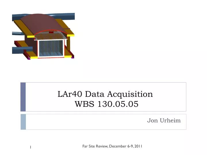
LAr40Data Acquisition WBS 130.05.05 Jon Urheim Far Site Review, December 6-9, 2011
Outline • Scope & Requirements • Technical overview • Interfaces to other LAr WBS & Conventional Facilities • Cost • Schedule • Summary Far Site Review, December 6-9, 2011 Jon Urheim
Scope • Configuration, control of detector operations • Exception: cryogenics system process control (will monitor though) • Generation/distribution of power & timing signals • Exceptions: High Voltage system for TPC & Low Voltage power supplies for front-end electronics systems. • Collection of data from TPC, Photon & Veto systems • Event building, filtering/triggering, fast processing • Slow controls, including detector & experiment conditions monitoring • Operator interface (Run Control) Far Site Review, December 6-9, 2011 Jon Urheim
Functional Requirements Deriving from U/S System Design • Disclaimer: please see CDR (& backup slides) for more expanded list of requirements beyond those tracked by project… • LAr40-DAQ-2: Configuration & Control Signals • DAQ will provide configuration & control signals to all detection systems • LAr40-DAQ-3: Data Interface to Detector Systems • DAQ shall receive raw data from a freely running readout from all detector systems • LAr40-DAQ-4: Time Stamp Accuracy • DAQ shall provide a time stamp to determine the time of occurrence of an event with an accuracy of 2.3 msec. (Max drift time for a 3.7 m drift is 2.3 ms) Far Site Review, December 6-9, 2011 Jon Urheim
Requirements derived from higher-level requirements • LAr40-7: Signal-to-noise Ratio – Distinguish MIP from noise w/ S/N > 9 • LAr40-DAQ-5: Noise Control – DAQ shall not inject unnecessary noise • LAr40-9:Detector Availability – LAr40 shall operate w/ >90% uptime • LAr40-DAQ-6: Deadtime & Pulse Time – DAQ shall limit deadtime to <1% for beam events & shall be able to correlate to event time in the detector. • LAr40-11: Data Collection Rate – LAr40 to collect data continuously • LAr40-DAQ-7: Continuous Data Collection – DAQ shall collect data continuously • LAr40-23: Collection of Burst Events – up to 10 kHz for 10 seconds with low deadtime • LAr40-24: Timing Accuracy – absolute time of occurrence of events with microsecond accuracy • LAr40-DAQ-8: Data Processing Speed – trigger on proton decay and supernova neutrino burst candidates requires prompt processing of data & accurate timing. Far Site Review, December 6-9, 2011 Jon Urheim
DAQ Overview:General Considerations • Withzero-suppressionin the front-ends, expect modest data rates through the DAQ despite high channel count (553k) and sampling rate (2MHz). • Suggests to exploit commodity commercial components & experience from other expt’s as much as possible. Use of ethernet switch arrays (as in D-Zero, CMS) is an obvious application. • NOvA provides a good model to consider for much of the system. • Comparable channel count (360k for 14kt NOvA, vs 553k for LAr40) • Similar beam signal timing properties & handling requirements • 2 MHz sampling at front-end, same as for LAr40, but event duration is short (scintillation signal) – fewms vs. 2.3ms. • On the other hand, per channel activity from cosmics & noise is high (surface detector):~100 Hz (mostly cosmics) vs.<100 Hz (1/2-MIP single channel salt & pepper from 39Ar, etc.) Far Site Review, December 6-9, 2011 Jon Urheim
DAQ Overview:Data Rates Rates/data sizes of dominating processes – All numbers are per APA – Zero-suppression assumed, unless noted otherwise – “Instantaneous data rates” are for2.3ms timeframe – “Avg data rates” factors in rate for ‘rare’ processes 1 APA (out of216) = 2.5m x 7m x (2 x 3.70m drift) = 178 tons LAr = 2560 read-out wires x4625 samples (@2 Msps) Far Site Review, December 6-9, 2011 Jon Urheim
DAQ System Data Flow Total: 108 APA’s/cryostat WBS 130.05.05 (DAQ) 1 APA (out of216) = 2.5m x 7m x (2 x 3.70m drift) = 178 tons LAr = 2560 read-out wires x4625 samples (@2 Msps) Far Site Review, December 6-9, 2011 Jon Urheim
DAQ Overview:Data Concentrator Module • Based on NOvA Design • Up to 64 inputs • Collects serial data • Combines and packetizes data for transmission to Data Farm nodes via ethernetswitch array. • Moredetail, next slide… Far Site Review, December 6-9, 2011 Jon Urheim
Data Concentrator Module • Based on NOvA Design • Up to 64 inputs, each 4 twisted pair (RJ-45) @24 Mbps. We could eliminate final 20-1 Mux stage in the cold volume, and deploy 1 DCM for every 2 APA’s. • This would give108DCM’s total (NOvA has 180), distributed geographically. • FPGA combines raw data from inputs • PowerPC processor (running linux) for configuration, buffering & routing • Processor generates ethernet packets • 1 x1Gbps (copper) ethernet out • NOvADCM’s now beingoperated at ‘Near Detector on Surface’ detector prototype. Far Site Review, December 6-9, 2011 Jon Urheim
DAQ Overview:Timing System • Based on NOvA Design • Central Facility: GPS receiver & Master timing unit • Distributed Components: Slave timing unit • Distributes synchronized clock signal to front-ends • More details, next slide… Far Site Review, December 6-9, 2011 Jon Urheim
Timing System • Also Based on NOvA Design • Note NuMI beam spill signal: • Spill length 10 ms, rep rate 2 s, similar to LBNE • Transmission to Minnesota via internet: typ latency 600 ms, and 99% transmission within 5s. Again can assume similar for LBNE. NOvA uses signal downstream of DCM’s in trigger farm/buffer nodes. • Above implies free-running (untriggered) readout through DCMs. • All FEBs must have synchronized clock signals • Timing system central facility: GPS receiver & Master timing unit • Distributed Components: slave ‘Timing Distribution Units’ • Distribute synchronized clock signal to front-ends via DCMs. • TOF/2 to account for propagation delay over timing backbone • Probably want 1 TDU for every 6 DCMs / 12 APAs, 18TDU’s total. • We may need to worry about propagation delay within the cryostat. Far Site Review, December 6-9, 2011 Jon Urheim
DAQ Overview:Ethernet Switch Array • Need to route data from DCM’s to Data Farm in Counting Room • More detail in backup Cisco 4948E Ethernet Switch 48 x1Gb in / 4 x10Gb optical out Cisco 6500 Router Chassis Series Far Site Review, December 6-9, 2011 Jon Urheim
DAQ Overview:Data Farm & Online Computing • Specifications: • 48 compute nodes • 100 TB staging disk system • More Details in Backup. Far Site Review, December 6-9, 2011 Jon Urheim
DAQ Overview:Power Requirements & Racks • In the Detector Hall: • ~15 kW power required for DAQ for each 25-kt cryostat • Relatively small number, O(10’s), of racks needed • Location is important (timing system) • Integrated with shielding/grounding plan • See presentation by Marvin Johnson for detail Far Site Review, December 6-9, 2011 Jon Urheim
Interfaces • TPC • DAQ provides: hardware and software for control & read-out • Scintillation Light Collection System • DAQ provides: hardware and software for control & read-out • Cosmic Ray Muon Veto System • DAQ provides: hardware and software for control & read-out • Cryogenics System • DAQ provides: software for data handling for run control monitoring task • Infrastructure and Installation • DAQ requires: Racks, with rack protection, cable trays, power, etc. Far Site Review, December 6-9, 2011 Jon Urheim
Cost Estimate Far Site Review, December 6-9, 2011 Jon Urheim
Labor vs M&S Far Site Review, December 6-9, 2011 Jon Urheim
Schedule (install by others) • Schedule provided by Ken CD-1: 6/2012 CD-2: 9/2013 CD-0: 1/2010 CD-3: 12/2014 Beneficial Occupancy: 10/2018 Designs Construction System Checkout Far Site Review, December 6-9, 2011 Jon Urheim
Milestones Far Site Review, December 6-9, 2011 Jon Urheim
Summary • The DAQ system design depends on detector/front-end electronics configurations. The design is in early phases relative to systems upstream. • Evaluation of physics/background rates & data sizes shows modest throughput requirement, despite high channel count/sampling rate. • A system exploiting commercial ethernet switch arrays is viable. • And, the main custom components (Data Concentrator Modules, Timing system) can be based on NOvA modules now being constructed/commissioned. • The LAr40 DAQ reference design is conservative, and could be built using components available today. Far Site Review, December 6-9, 2011 Jon Urheim
Answer to Reviewer Questions:LAr-6: # Software Professionals (1) • What is the number of software professionals required for the LAroption? How do you cost the total number you need? (1) To manage & monitor data flow through the DAQ, software is needed for DCM FPGA and Processor operations, for DCMswitch array farm node supervision/monitoring, etc., and for Display/Control functions of the Run Control system. This is divided among DAQ and Detector Monitoring & Control WBS items This effort is included in our allowance of 7 FTEs x 1yr during construction and 2.5 FTEs x 1yr during “checkout” phases for DAQ, and 2.5 FTEs x 2 yrs during construction and 1.5 FTEs x 2yrs during checkout for for DetMon. The corresponding resources listed in the BOEs are Electronics Engineers, Electronics Technicians, and Physicists, but some fraction of this should probably be Software Professionals – the division of labor between hardware and software is somewhat blurry for DAQ. It is worth noting that some of this development will also be done during the design phase, with prototyping in the context of LAr1, and there is separate labor included under the LAr1 scope. (2) See next slide for discussion of software within the data farm, including online fast processing (analysis) of data… Far Site Review, December 6-9, 2011
Answer to Reviewer Questions:LAr-6: # Software Professionals (2) • What is the number of software professionals required for the LAroption? How do you cost the total number you need? (2) A portion of the DAQ system scope involves use of software to trigger/filter data in the data farm and to provide data quality information to shifters/archival. It is assumed that some portion of this task will employ the offline data analysis software framework (LArSoft), which is being developed and maintained outside the DAQ scope (and in large part outside the LBNE scope). Hence we have not counted the effort needed to develop and maintain this software. This contrasts with the scope of the WCD WBS, which includes 1 FTE of software professional labor throughout the Project for such support for both online & offline computing, within their “Computing” WBS item, for which we have no analog at present. The actual implementation of event-building, trigger, filter functionality incorporates a fraction of the labor listed on the previous slide. It may be prudent to add something like 0.5 FTE of computing professional time to construction and checkout phases of the project to assist with this portion of the DAQ implementation. Far Site Review, December 6-9, 2011
Backup Slides Far Site Review, December 6-9, 2011 Jon Urheim
DAQ System Requirements (1) • Signals to and from detector elements • Provide configuration/control signals to TPC, Photon & Veto. • Collect raw data viainterface withfront-end electronics • Continuous 2-MHz sampling at the front-ends, 12-bit ADC. • Zero-suppression in the TPC front-ends • 2.3 ms maximum ionization drift time • Timing • Generate time stamps with sub-microsecond accuracy • May need to revise if neutrino TOF added to LBNE science scope • Distribute synchronized clock signals • Incorporate LBNE beam spill signal information Far Site Review, December 6-9, 2011 Jon Urheim
DAQ System Requirements (2) • Event building, filtering and storage • Unpack, assemble data into single event records • Note free-running data flow from front-ends • Note2.3ms maximum drift & approximate readout block times • DAQ must handle events spanning multiple readout blocks. • Event record format must be amenable to data analysis • DAQ must compute & apply event selection criteria • Local temporary data storage & protocol for transfer off-site • Pulsing/testing of front-end electronics • Initiate, collect, record detector checkout data • DAQ must be operational during electronics installation & commissioning Far Site Review, December 6-9, 2011 Jon Urheim
DAQ System Requirements (3) • Run Control and Data Monitoring • Allow experimenters to operate detector • Monitor data collection integrity & data quality • Slow Controls • Interface withhardware operating in support of detector systems (power supplies, etc.). • Monitor detector, subsystems, environmental conditions • Interface withcryogenics process control systems to provide information to operators/collaborators and to generate appropriate interlock signals with regard to detector operations Far Site Review, December 6-9, 2011 Jon Urheim
NOvA Data Flow & Triggering Far Site Review, December 6-9, 2011 Jon Urheim
NOvA Data Flow & Triggering Far Site Review, December 6-9, 2011 Jon Urheim
Component Count (1 cryostat) Far Site Review, December 6-9, 2011 Jon Urheim
CISCO 4948E Ethernet Switch Cisco 4948E Ethernet Switch – 48 x1Gb in – 4 x10Gb optical out – 175 MB memory: automatically buffers data if link is in use • Located in Detector Hall • Nominally switchesdata from27DCMs • DCMs just send packets • Optical uplink to Counting Room Far Site Review, December 6-9, 2011 Jon Urheim
Cisco 6509 E Router System • Located in Counting Room (on surface). • Utilize Cisco 6509 E chassis • 1x8-port10Gb blade • Input from 2 x 4948E’s • 1 x 48-port 1 Gbblade • Output to data farm Cisco 6500 Router Chassis Series Far Site Review, December 6-9, 2011 Jon Urheim
Data Farm & Online Computing • CPU: • 48 compute nodes for event building/triggering • Output to data logger / disk farm • To account for events spanning multiple time blocks, will need to send data for a given block to two (or three) separate nodes, so that a given node has data for blocks (N-1), (N) and (N+1). • Disk farm: • 100 TB staging disk system in preparation for transfer of data off-site via internet. • Should be sufficient to store triggered data for 5 days (even if no prescaling of CR muons) Far Site Review, December 6-9, 2011 Jon Urheim
Network/Data Flow Management • Routing Master • Tracks availability of farm nodes & provides routing info to DCMs • Supervisor • Interface with farm nodes: downloads, collation of statistics, results from processing of data. Far Site Review, December 6-9, 2011 Jon Urheim
1 2 8 1 2 3 4 5 3 6 1 1 2 3 4 5 6 7 4 5 4 7 6 5 6 7 8 1 2 3 4 5 6 7 8 1 2 3 7 6 8 3 1 2 3 4 5 6 7 8 8 2 3 4 5 6 7 8 2 7 5 5 8 5 6 7 8 1 2 3 4 6 4 7 8 1 2 3 4 1 NOvA DAQ Overview The animation on this slide demonstrates the existing round-robin scheme for sending data from DCMs to buffer nodes. • All of the fragments for a given event are sent from all of the DCMs to the same buffer node at essentially the same time. • The destinationbuffer node is determined by a fixed algorithm (fixed schedule). • Discuss variability in arrival at buffer node… (delay in sending; delay in transmission) Kurt Biery
Bandwidth Table • Assume20Mbps out from each APA (39Ar) • So1.0Mbps per FEB (128 wires) into each DCM input port • Comfortable headroom at every stage Far Site Review, December 6-9, 2011 Jon Urheim
Some Cost Examples • Data Concentrator Modules: • NOvA costs: 2.2 k$ per DCM • 54modules needed + spares ~150k$ (one cryostat) • Networking: • Cisco 4948 E: 2 @ 12 k$ 24 k$ (one cryostat) • Cisco 6509 + 2 blades: 43 k$ (one cryostat) • Disk Farm: • A 100 TB system today would be 100-150 k$ • Looking ahead, conceivably such a system would be packaged as 2 x Raid-6 arrays of 8 x 10 Tbyte disks (incl. parity & spares), and would be cheaper by a factor of 2-3 (or more). Far Site Review, December 6-9, 2011 Jon Urheim