Download
1 / 40
450 likes | 702 Views
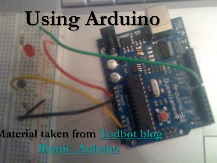
Using Arduino. Material taken from Todbot blog Bionic Arduino. What is the Arduino. Arduino Duemilanove. 13 digital input/output pins Including 6 with PWM for analog output 6 analog input pins USB connection For serial I/O and uploading board ATmega168 or ATmega328 processor

E N D
Using Arduino Material taken from Todbot blog Bionic Arduino
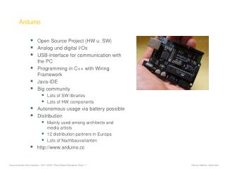
Arduino Duemilanove • 13 digital input/output pins • Including 6 with PWM for analog output • 6 analog input pins • USB connection • For serial I/O and uploading board • ATmega168 or ATmega328 processor • 16k or 32k for program, 1k or 2k for data • Arduinobootloader • ~ $30 • More Info
Other Arduino Boards • Arduino Mega • Lots of I/O pins and lots (128k) of program space • ~ $65 • LilyPad • For wearable applications • ~ $20 • Boarduino • Fits within a breadboard • ~ $20, but must be soldered!
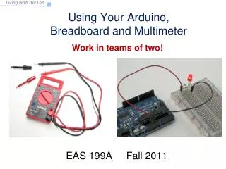
Activity 1 • Start the Arduino IDE from the terminal window with the command: arduino • Make sure to connect the PC to the Arduino using the USB cable. • Designate the connection port and processor type. • Try out the “blink” example • Select: File > Examples > Digital > Blink
Select Connection and Type atmega328
Activity 1 Modified---Add an External LED to pin 13 • File > Examples > Digital > Blink • LED’s have polarity • Negative indicated by flat side of the housing and a short leg www.instructables.com
Arduino Control • Very much like Processing/Java • if, then, while, switch • Functions, expressions • setup() • Runs once at beginning (or reset) • loop() • Runs continuously • Like draw()
Arduino Digital I/O • pinMode(pin, mode) • Sets pin to either INPUT or OUTPUT • digitalRead(pin) • Reads HIGH or LOW from a pin • digitalWrite(pin, value) • Writes HIGH or LOW to a pin • Electronic stuff you can ignore • Output pins can provide 40 mA of current • Writing HIGH to an input pin installs a 20KΩ pullup
Arduino Timing • delay(ms) • Pauses for a few milliseconds • delayMicroseconds(us) • Pauses for a few microseconds
Breadboard Fundamentals There are ten holes that form the rows. These are divided into two sets of five holes. All holes in each set of five are connected Connect this column to GND (0 volts) Connect this column to 5V All holes in each of the four long columns are connected internally. Use these to route power and ground. Connect this column to GND (0 volts) Connect this column to 5V
Activity 2 • File > Examples > Digital > Melody • Speakers have polarity. Positive indicated by small + or dot on piezoelectric speaker.
Activity 2 • Get a breadboard and a piezoelectric speaker • Assemble as shown Image credit: Tod Kurt • Try out the built-in “melody” example • Select: File > Examples > Digital > toneMelody • Try this version of Melody.pde
Digital? Analog? Digital has two values: on and off Analog has many (infinite) values Computers don’t really do analog, they quantize Remember the 6 analog input pins---here’s how they work Image credit: Tod Kurt
Analog to Digital Number of states or “bins” is the resolution Arduino resolution is 10-bits (1024 values) 5/1024 = 4.8 mV smallest voltage change you can measure Image credit: Eoin Brazil
Analog Output Computers can’t output analog voltages Only digital voltages (0 volts or 5 volts) Simulating an analog signal with Pulse Width Modulation (PWM) Can’t directly supply 2.5V, but can pulse the output on and off really fast to produce the same effect---the same effective voltage.
Analog Output Vary the effective voltage by modulating the width of the high pulse Image credit: Tod Kurt
Activity 3 Image credit: Tod Kurt • Select: File > Examples > Analog > Fading • Hardware Needed: • Resistor (in 220-500 Ohm range) • Breadboard • LED • Wire • Assemble as shown (MOVE the piezo speaker to pin 7)
PWM is Everywhere Lamp dimmers, motor, speed control, power supplies, noise making, etc. Now on to analog input using sensors---DON’T DISASSEMBLE your breadboards
Sensing the Dark: Photoresistors a.k.a. a photocell or light-dependent resistor It is a variable resistor Brighter light => lower resistance Create a voltage divider to use the photoresistor Image credit: Tod Kurt
Activity 4 Image credit: Tod Kurt • Hardware Needed: • Resistor (approx. 10k Ohm) • Breadboard • Photoresistor • Wire • Assemble as shown
A Theremin Create a theremin using the photoresistor A spooky sound machine Works by measuring your body’s electric field We’ll use light to control the tone produced We’ll also control the brightness of the LED using the photoresistor. Verify your breadboard configuration!
Theremin Breadboard Configuration Hardware Needed: Resistors, Breadboard, Wire, Photoresistor, Piezo speaker, LED
The Theremin Program Load and run the TherminAndLED program
Sensors There are many analog sensors that could be used in place of the photoresistor Check out our “theremin” demos created using other sensors Image credit: Tod Kurt
Arduino Program Processing Program Serial (TTL) Communication Your Computer Arduino Board Communication Between the Arduino and Your Computer
Processing • Includes libraries supporting serial communication, video capture, audio processing… • VERY IMPORTANT: enter the following command in the terminal window to update the serial library: ~brock/bin/serialfix • Start Processing from the terminal window
Activity 5 Image credit: Tod Kurt • Hardware Needed: • Resistor (10k Ohm) • Breadboard • Photoresistor • Wire • Don’t reassemble - this is the same schematic as Activity 4.
Activity 5 Open SimpleWrite.pdeinto the Arduino IDE. Open SimpleRead.pde into Processing.
Clarifications • SimpleWrite spends the first second sampling the photocell readings and setting limits. • The Arduino program restarts when the Processing program starts. • If the Processing program begins behaving badly, try pressing the restart button on the Arduino.
Project 2 • Project 2