Download
1 / 3
90 likes | 169 Views
According to the World Federation of the Deaf, only 10 percent of the worlds Deaf population receives any education, and only 3 percent receives this education in sign language. Another problem these deaf and face is inability to communicate with a person who does not understand the sign language. This project aims to reduce these problems by presenting a Sign Language. The project uses a hepatic glove to acquire signals corresponding to various hand gestures. The glove is interfaced with robot using an Arduino. Accelerometers are used to measure the angular displacement of human hand motion .The accelerometer controls the movement of the robot. Device is made of mainly two parts, one is RF transmitter and another is RF receiver. The RF transmitter will transmit the signal according to the position of accelerometer attached on your hand and the RF receiver will receive the signal and make the robot move in respective direction. Deepanshu Kiran | Himanshu Singh | Kushal Kant Singh Saxeriya "Gesture Control Robot using Arduino" Published in International Journal of Trend in Scientific Research and Development (ijtsrd), ISSN: 2456-6470, Volume-3 | Issue-3 , April 2019, URL: https://www.ijtsrd.com/papers/ijtsrd23411.pdf Paper URL: https://www.ijtsrd.com/engineering/electrical-engineering/23411/gesture-control-robot-using-arduino/deepanshu-kiran<br>

E N D
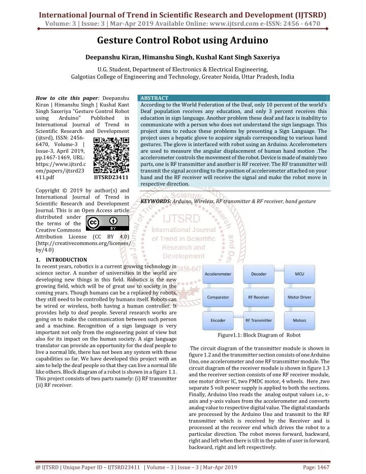
International Journal of Trend in Scientific Research and Development (IJTSRD) Volume: 3 | Issue: 3 | Mar-Apr 2019 Available Online: www.ijtsrd.com e-ISSN: 2456 - 6470 Gesture Control Robot using Arduino Deepanshu Kiran, Himanshu Singh, Kushal Kant Singh Saxeriya U.G. Student, Department of Electronics & Electrical Engineering, Galgotias College of Engineering and Technology, Greater Noida, Uttar Pradesh, India How to cite this paper: Deepanshu Kiran | Himanshu Singh | Kushal Kant Singh Saxeriya "Gesture Control Robot using Arduino" Published in International Journal of Trend in Scientific Research and Development (ijtsrd), ISSN: 2456- 6470, Volume-3 | Issue-3, April 2019, pp.1467-1469, URL: https://www.ijtsrd.c om/papers/ijtsrd23 411.pdf Copyright © 2019 by author(s) and International Journal of Trend in Scientific Research and Development Journal. This is an Open Access article distributed under the terms of the Creative Commons Attribution License (CC BY 4.0) (http://creativecommons.org/licenses/ by/4.0) 1.INTRODUCTION In recent years, robotics is a current growing technology in science sector. A number of universities in the world are developing new things in this field. Robotics is the new growing field, which will be of great use to society in the coming years. Though humans can be a replaced by robots, they still need to be controlled by humans itself. Robots can be wired or wireless, both having a human controller. It provides help to deaf people. Several research works are going on to make the communication between such person and a machine. Recognition of a sign language is very important not only from the engineering point of view but also for its impact on the human society. A sign language translator can provide an opportunity for the deaf people to live a normal life, there has not been any system with these capabilities so far. We have developed this project with an aim to help the deaf people so that they can live a normal life like others. Block diagram of a robot is shown in a figure 1.1. This project consists of two parts namely: (i) RF transmitter (ii) RF receiver. ABSTRACT According to the World Federation of the Deaf, only 10 percent of the world's Deaf population receives any education, and only 3 percent receives this education in sign language. Another problem these deaf and face is inability to communicate with a person who does not understand the sign language. This project aims to reduce these problems by presenting a Sign Language. The project uses a hepatic glove to acquire signals corresponding to various hand gestures. The glove is interfaced with robot using an Arduino. Accelerometers are used to measure the angular displacement of human hand motion .The accelerometer controls the movement of the robot. Device is made of mainly two parts, one is RF transmitter and another is RF receiver. The RF transmitter will transmit the signal according to the position of accelerometer attached on your hand and the RF receiver will receive the signal and make the robot move in respective direction. KEYWORDS: Arduino, Wireless, RF transmitter & RF receiver, hand gesture IJTSRD23411 Figure1.1: Block Diagram of Robot The circuit diagram of the transmitter module is shown in figure 1.2 and the transmitter section consists of one Arduino Uno, one accelerometer and one RF transmitter module. The circuit diagram of the receiver module is shown in figure 1.3 and the receiver section consists of one RF receiver module, one motor driver IC, two PMDC motor, 4 wheels. Here ,two separate 5 volt power supply is applied to both the sections. Finally, Arduino Uno reads the analog output values i.e., x- axis and y-axis values from the accelerometer and converts analog value to respective digital value. The digital standards are processed by the Arduino Uno and transmit to the RF transmitter which is received by the Receiver and is processed at the receiver end which drives the robot to a particular direction. The robot moves forward, backward, right and left when there is tilt in the palm of user in forward, backward, right and left respectively. @ IJTSRD | Unique Paper ID – IJTSRD23411 | Volume – 3 | Issue – 3 | Mar-Apr 2019 Page: 1467
International Journal of Trend in Scientific Research and Development (IJTSRD) @ www.ijtsrd.com eISSN: 2456-6470 Figure1.2: Circuit Diagram of Transmitter Figure1.3: Circuit Diagram Of Receiver 2.LITERATURE REVIEW Using Teach box for Programming and control of a robot is a difficult and time-consuming task that requires technical knowledge. Therefore, the approach is to have new and more natural ways for programming & control of robot. In the robotics field, numerous research efforts have been made to create user-friendly teach pendants, implementing user boundaries such as color touch screens, a 3D joystick. But, these techniques are not resourceful to control the robot as they do not give correct results and provide slow response time. In the past years the constructors of robot have made efforts for forming “Human Machine Interfacing Device”. Using gesture controlled concept, it is possible to move a robot accordingly. Accelerometers are the main technologies used for human machine interaction that offer very reasonable motion sensitivity in different applications. Motion technology creates easy for humans to interact with machines naturally without any interventions caused by the drawbacks of mechanical devices. Accelerometer-based gesture recognition has become progressively popular over the last decade compared to vision based technique. The factors that make it an operational tool to detect and recognize the human gestures are its low-moderate cost & relative small size of the accelerometers. 3.Types of Components 3.1.Arduino Arduino Uno is a microcontroller board based on ATmega328 which has 14 digital I/O and 6 analog pin. It has everything that is needed to support the microcontroller. Simply connect it to the computer with a USB cable to get started with the Arduino Uno board. It is simple easy to use hardware and software. Arduino can sense the atmosphere by receiving input from a diversity of sensors and can affect its environment by controlling lights, motors, and other actuators. 3.2.Accelerometer (ADXL335) The ADXL335 is a little, slim, low power, complete accelerometer with signal conditioned voltage outputs. It has 6 pins. 3 pins is for X, Y, Z axis. First pin for power supply (VCC), second pin for ground (GND) and the last one for selftest (ST). It operates on 3.3V from the Arduino Uno board. X and Y axis pins are connected to A0 and A1 pin of Arduino respectively. It can determine the static acceleration of gravity from angle sensing applications as well as dynamic acceleration resulting from motion, shock or vibration and gives corresponding analog values through X, Y, Z axis pins. The ADXL335 is available in a small, low profile, 4mm x 4mm x 1.45 mm, 16-lead, plastic lead frame chip scale package. 3.3.Motor Driver Motor Driver works on the concept of H-bridge. H-bridge is a circuit which permits the voltage to flow in either direction. As voltage needs to change its direction for being able to turn the motor in clockwise or anti-clockwise direction. So H- bridge IC is ideal for driving a DC motor. In a single L293D @ IJTSRD | Unique Paper ID - IJTSRD23411 | Volume – 3 | Issue – 3 | Mar-Apr 2019 Page: 1468
International Journal of Trend in Scientific Research and Development (IJTSRD) @ www.ijtsrd.com eISSN: 2456-6470 chip there are two h-Bridge circuit within the IC which can turn two dc motor independently. Due to its small size it is very much used in robotic application for controlling DC motors. 3.4.DC Motor DC motor is used to change direct current into mechanical motion. The motion could be rotary or linear. The operation of DC motor is depended on the principle that when a current carrying conductor is placed in a magnetic field, the conductor experiences a mechanical force. The speed of a DC motor can be controlled by varying the voltage applied to the armature or by varying the field current. DC motor can be used for the movement of the robotic system. 3.5.Battery A battery is a electric tool made of one or more electrochemical cells. A battery is device that directly converts chemical energy into the electrical energy. The principle of battery is to supply 12 volts to operate DC motors. 3.6.RF Transmitter & Receiver The transmitter section is working on the frequency of 433MHz. In the circuit, Vcc pin is connected to the + terminal and data pin is connected to the HT12E (Encoder) that is transmitted or we can say that encoded data. The next pin is GND that is linked to the ground terminal. Now the last pin ANT this is linked to a small wire as an antenna. The RF receiver will get the data which is transferred by the gesture device. It is also working as similar to the transmitter module- attach the +Vcc pin to the 5volt terminal. link the ground pin to the ground terminal .The data pin is then linked to the HT12D (Decoder) .So that we can get the decoded 4 bit data. 3.7.Camera An image acquiring device which provides the video required for vision. In this project, we are using mi wireless camera. 4.Conclusion Radio frequency transmission is used instead of infrared transmission as RF can travel longer distance which improves the range of application, RF can even work in obstruction between remotes and car. The RF module has a range of 20- 30 meters. This robot can be modify to detect human life in earthquake and landslide by implementing the sensor accordingly. It can also be used to bomb detecting robot. GPS system can be add to the robot by the help of which its location can be tracked. 5.Future scope In the receiver section a wireless camera is placed to check the performance of robot. The on board batteries use a lot of space and are also quite heavy. We can either use some alternate power for the batteries or replace the DC Motors with ones which use less power. Most videogames are played either on game consoles or PCs, and all require a mixture of input devices. Gesture recognition can be used to truly engage a player in the game world like never before. In homes, offices,vehicles and more, gesture controlling can be combined to greatly increase usability and decrease the resources required to create primary or secondary input systems like remote controls, car entertainment systems with buttons or similar. Reference [1]Premangshu Chanda, SubrataModak, AsokeNath, “Gesture Controlled Robot using Arduino and Android”, IJARCSSE, Volume 6, Issue 6, June 2016. PallabKanti Mukherjee, [2]P. V. Patil, M. B. Shete, T. M. Padalkar, “Wireless Hand Gesture Robot using Accelerometer, Volume: 03 Issue: 04 , Apr-2016. [3]Saurabh A. Khajone, Dr. S. W. Mohod, V.M.Harne “Implementation of a Wireless Gesture Controlled Robotic Arm” in IJIRCCE Vol. 3, Issue 1, January 2015. [4]Vivek Bhojak, Girish Kumar Solanki, Sonu Daultani “Gesture Controlled Mobile Robotic Arm Using Accelerometer” in IJIRSET Vol. 4, Issue 6, June 2015. [5]SwarnaPrabha Jena, Sworaj Kumar Nayak, Saroj Kumar Sahoo, Sibu Ranjan Sahoo, Saraswata Dash, Sunil Kumar Sahoo ,“Accelerometer Based Gesture Controlled Robot Using Aurdino” IJESRT. [6]Archika Setia, Surbhi Mittal, Padmini Nigam,Shalini Singh, Surendra Gangwar “Hand Gesture Recognition Based Robot Using Accelerometer Sensor” in IJAREEIE in Vol. 4, Issue 5, May 2015 @ IJTSRD | Unique Paper ID - IJTSRD23411 | Volume – 3 | Issue – 3 | Mar-Apr 2019 Page: 1469