Download
1 / 16
160 likes | 290 Views
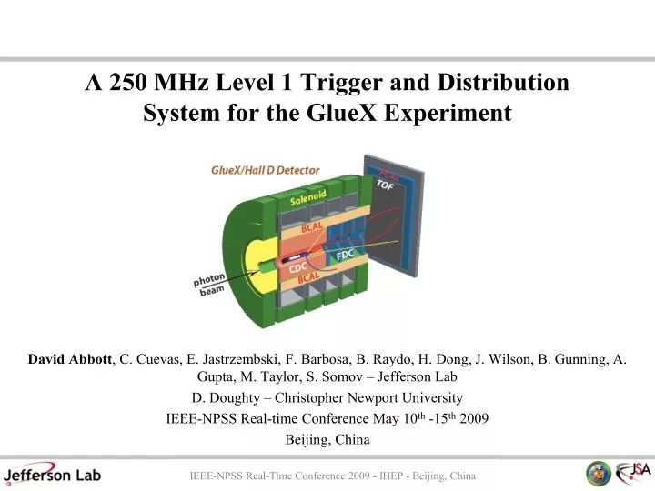
A 250 MHz Level 1 Trigger and Distribution System for the GlueX Experiment. David Abbott , C. Cuevas, E . Jastrzembski , F. Barbosa , B. Raydo , H. Dong, J. Wilson, B. Gunning, A. Gupta, M. Taylor, S. Somov – Jefferson Lab D. Doughty – Christopher Newport University

E N D
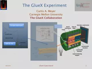
A 250 MHz Level 1 Trigger and Distribution System for the GlueX Experiment David Abbott, C. Cuevas, E. Jastrzembski, F. Barbosa, B. Raydo, H. Dong, J. Wilson, B. Gunning, A. Gupta, M. Taylor, S. Somov– Jefferson Lab D. Doughty – Christopher Newport University IEEE-NPSS Real-time Conference May 10th -15th2009 Beijing, China IEEE-NPSS Real-Time Conference 2009 - IHEP - Beijing, China
Introduction • Jefferson Lab (in Newport News Virginia) has begun construction on an upgrade to the existing electron accelerator. • Double the energy – 6 GeV -> 12 GeV • Fourth experimental area (Hall D) • Completion by 2015 • The new experimental Hall will house the GlueX detector • New experimental program will require upgrades to existing DAQ and trigger systems. All experimental halls share a common DAQ system (CODA). • New designs are being introduced into the existing 6 GeV program. IEEE-NPSS Real-Time Conference 2009 - IHEP - Beijing, China
GlueX detector Photon Beam dump Radiator 75 m Top View e- Collimator Electron beam dump Tagger Area Coherent Bremsstrahlung photon beam GlueX Experiment Physics goal: Search for exotic mesons in interactions of polarized photons with a hydrogen target Exp. Hall • Bremsstrahlungphotons produced by 12 GeV electron beam incident on a diamond crystal. Main coherent Bremsstrahlung peak at E 8.4 – 9.0 GeV • Two classes of interactions in the detector: • - Hadronicphotoproduction (on 30 cm long liquid hydrogen target) • - Electromagnetic interactions IEEE-NPSS Real-Time Conference 2009 - IHEP - Beijing, China
GlueX Trigger Total Photon flux : 3 x10^9 (10^8 in coherent peak) Total Hadronic Rate: 360 kHz Total Elecromagnetic background: ~200 MHz (Compton + pair production in target/detector) Trigger:Level 1 (Hardware) + Level 3 (Software) L1 Goal: < 200 kHz (with high efficiency for coherent photoproduction) Total Channels: ~22k L1 Data rate: ~3 GB/sec L3 Farm: 20 kHz, 300 MB/s to Disk Detector subsystems: Tagger (L1) Pair spectrometer Start Counter (L1) Central Drift Chamber Forward Drift Chambers Time of Flight (L1) Barrel Calorimeter (L1) Forward Calorimeter (L1) Coherent peak 8.4 < E < 9.0 L1 L3 IEEE-NPSS Real-Time Conference 2009 - IHEP - Beijing, China
Level 1 Design • Up to 5 detector subsystems can be used • FCAL/BCAL – Energy • Start Counter – Hits • Forward TOF – Hits • Tagger – Hits (not at high luminosity) • Continuous computation (@250 MHz) • 4 level hierarchy • Board -> Crate -> Subsystem -> Global • VME for the Data Path (2eSST : >200 MB/s) • VXS for the Trigger Path • 18 payload slots • 2 switch slots (redundant star) • 8 serial lanes (4 each in/out) per VME slot • Board level trigger starts with custom JLAB • design flash ADC (250 MHz)… VXS (VITA 41 standard) VME64x + high speed serial fabric on J0 IEEE-NPSS Real-Time Conference 2009 - IHEP - Beijing, China
T T FADC FADC FADC JLAB 250 MHz Flash ADC • Pipeline trigger/data (8 microseclookback) • User downloadable (via VME) code for Input/Trigger FPGAs Trigger FPGA (Xilinx FX20) x8 Input FPGA (Xilinx LX25) Sums & Hits VXS (P0) Rocket I/O Aurora protocol x2 lanes bonded 2.5 Gbps/lane 8/10 bit encoding Data: 500 MB/s Trigger Data & Control (AlteraStratix II) 5 4 3 VME 16 Inputs (10 or 12 bit) @ 250 MHz 2 2eSST Data: 200 MB/s 1 IEEE-NPSS Real-Time Conference 2009 - IHEP - Beijing, China
Crate Level Processing CTP Prototype • Crate Trigger Processor (CTP) • Switch slot A • Accept 16 FADC streams via VXS • Crate Sum & Hit processing • x4 lane (1 GB/s total) fiber out to • sub-system level • Trigger Interface (TI) • Payload slot 18 • Accepts Global Trigger/Clock/Sync Info • Fixed Latency link (16 bits @ 62.5 MHz) • Sends trig data to SD for crate distribution • Accepts CTP info for VME readout • Signal Distribution Card (SD) • Switch slot B • Distribute (via VXS) Clocks/Trigger/Sync • to all boards in the crate. Virtex5 LX50 HFBR-7934 fiber trans. C T P T I C P U S D Virtex5 LX110 FADC FADC VXS Crate IEEE-NPSS Real-Time Conference 2009 - IHEP - Beijing, China
Sub-System Processor (SSP) • All SSPs reside in a single VXS crate (Global Trigger Crate) • Each SSP receives up to 8 four-lane CTP links • Multiple SSPs will be needed for some Detector systems • Each SSP clock time-stamped reports to Global Trigger Processor (via x4 lane VXS) • Prototype designs are in progress GlueX L1 Systems: BCAL: 2 SSPs FCAL: 2 SSPs SC : 1 SSP TOF : 1 SSP TAG : 1 SSP IEEE-NPSS Real-Time Conference 2009 - IHEP - Beijing, China
Global Trigger Processor (GTP) Switch Slot – up to 2 GTPs in the Crate Up to 32 independent trigger decisions every 4 ns Data sent to Trigger Distribution Crate… IEEE-NPSS Real-Time Conference 2009 - IHEP - Beijing, China
Global Trigger Processing cont… To estimate the latency involved in calculation of an L1 trigger by the GTP an example equation was implemented in VHDL using Xilinx synthesis tools and a Virtex 5 LX220 FPGA: FCAL BCAL TOF T I C P U G T P G T P • Z >= TFM*HTOF + EFM*EFCal + RM*((EFCal +1)/(EBCal + 1)) • HTOF - Hits Forward TOF • EFCal - Energy Forward Calorimeter • EBCal - Energy Barrel Calorimeter • All computing done in pipelined, 32bit floating point arithmetic • SSP data was converted from integers to floating point • Equation is computed every 4ns and trigger bit is updated if Z is above a programmable threshold • Each coefficient is “variable” – can be changed very quickly without having to reprogram FPGA • Used Xilinx specific math libraries (+, -, *, /, sqrt) • Synthesis and implementation resulted in using only 3% of LX220 FPGA • Latency was 69 clock cycles => 276ns delay introduced for forming L1 trigger to TS SSP SSP IEEE-NPSS Real-Time Conference 2009 - IHEP - Beijing, China
Trigger Distribution • Trigger Supervisor (TS) • Accept trigger decision from GTP (ribbon/copper) • Async User triggers – pulsers/calibration • Source for global 250 MHz Clock • Serialize trigger :16bits @ 62.5 MHz (every 16 ns) • “Master” TI board – payload slot 18 • Trigger Distribution Cards (TD) • up to 16 total (in payload slots 2-17) • Fan-out clock/trigger/sync to 1-8 crates (to TI) • Uses same fiber connections as CTP->SSP links • Ensure fixed-latency link for trigger to all front-end crates • Synchronizes 250 MHz clock on all crates • Return data link provides crate status – error or busy condition • that would require triggers to be disabled. S D C P U T S TD TD IEEE-NPSS Real-Time Conference 2009 - IHEP - Beijing, China
L1 Trigger & Distribution Global Trigger Crate Trigger Distribution Crate Distribute Trigger: up to 128 crates T S S D C P U T I C P U G T P G T P 32 bits @ 250MHz 64 bits @ 125MHz (x4 2Gb/s Link) TD TD SSP SSP 16 bits @ 62.5MHz (x1 1Gb/s Link) Front-End Crates: (~50 VXS, 12 VME) VXS Links: x2 2Gb/s IEEE-NPSS Real-Time Conference 2009 - IHEP - Beijing, China
Level 1 Trigger Timing t1 t2 t3 t4 t5 t6 t7 FADC250 CTP SSP GTP Global Trigger Crate Link: 32bits @ 125MHz BCal, FCal Mode: 15:0 ADCSum t0 31:16 ADCSum t1 TOF, ST, Tagger Mode: 15:0 Hit Bits t0 31:16 Hit Bits t1 Link: 64bits @ 125MHz BCal, FCal Mode: 19:0 ADCSum t0 39:20 ADCSum t1 TOF, ST Mode: 8:0 TrackCount t0 17:9 TrackCount t1 39:18 Unused Tagger Mode: 7:0 MinHit t0 15:8 MaxHit t0 23:16 MinHit t1 31:24 MaxHit t1 39:32 Unused All Modes: 47:40 Timestamp 63:48 ECC Link: 64bits @ 125MHz BCal, FCal Mode: 22:0 ADCSum t0 55:23 ADCSum t1 63:56 Unused TOF, ST Mode: 11:0 TrackCount t0 23:12 TrackCount t1 63:24 Unused Tagger Mode: 7:0 MinHit t0 15:8 MaxHit t0 23:16 MinHit t1 31:24 MaxHit t1 63:32 Unused t8 Link: 32bits @ 250MHz 31:0 Triggers(31:0) TS t18 Front-end Crate t9 Link: 3bits @ 250MHz 0 Trigger 1 1 Trigger 2 2 Sync Trigger Distribution Crate Link: 16bits @ 62.5MHz 15:0 TriggerWord SD TI TD SD t17 t16 t15 t14 t13 t12 t11 t1: FADC250 (ADC->P0) 180ns (20cycles+100ns MGT) t11: SD (Px->Px) 10ns t2: FADC250->CTP (P0->Px) 10ns t12: SD->TD (Px->P0) 10ns t3: CTP (Px->FiberTx) 180ns (20cycles+100ns GTP) t13: TD (P0->FiberTx) 10ns t4: CTP FiberTx->SSP FiberRx 600ns (~100m fiber run) t14: TD->TI (FiberTx->Fiber Rx) 600ns (~100m fiber run) t5: SSP (FiberRx->P0) 600ns (100cycles+200ns GTP) t15: TI (FiberRx->P0) 80ns (20cycles) t6: SSP->GTP (P0->Px) 10ns t16: TI->SD (P0->Px) 10ns t7: GTP (Px->TrigBit) 495ns (95cycles+100ns GTP) t17: SD (Px->Px) 40ns t8: GTP->TS (TrigBit->TrigBitIn) 10ns t18: SD->FADC250 (Px->P0) 10ns t9: TS (TriggerBitIn->P0) 115ns (20cycles+35ns SerDes) t10: TS->SD (P0->Px) 10nsTotal: 2980ns IEEE-NPSS Real-Time Conference 2009 - IHEP - Beijing, China
GlueX DAQ Overview 300 MB/sec 15-20 KHz 3 GB/sec IEEE-NPSS Real-Time Conference 2009 - IHEP - Beijing, China
Prototypes & Testing • Two crate system • Crate-level summing (4 Flash ADCs) • 250 MHz clock distribution • Trigger distribution/ synchronization (up to 150 meters) Please visit Poster TDAP-16 for more information CTP FADC TS SD FADC TI IEEE-NPSS Real-Time Conference 2009 - IHEP - Beijing, China
Summary • The 12 GeV upgrade and a new experiment (GlueX) at Jefferson Lab requires significant performance improvements for both trigger and data acquisition. • We must transition with support for legacy systems in the other experimental halls - VXS. • Implement deadtimeless pipelined front-end digitizers with synchronous 250 MHz Level 1 trigger and distribution system. • L1 requirements (200 kHz, < 4 µs) latency can be met. • Customized L1 systems can be built from for all experiments using Board -> Crate -> Sub-system -> Global hierarchy • Prototyping and testing have been successful without pushing the bandwidth limits of the technology. There is much room for expansion. IEEE-NPSS Real-Time Conference 2009 - IHEP - Beijing, China