Download
1 / 36
360 likes | 475 Views
The Trigger System of the MEG Experiment. On behalf of D. Nicolò F. Morsani S. Galeotti M. Grassi. Marco Grassi INFN - Pisa. Background Rate Evaluation. COBRA magnet. Simulation Simulation with GEANT 3.21 Proposal geometry Contribution correlated: irrelevant accidental: main

E N D
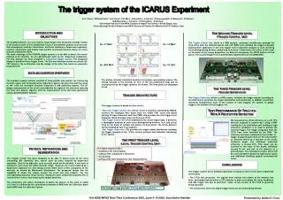
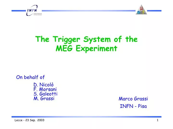
The Trigger System of the MEG Experiment On behalf of D. Nicolò F. Morsani S. Galeotti M. Grassi Marco Grassi INFN - Pisa
Background Rate Evaluation COBRA magnet • Simulation • Simulation with GEANT 3.21 • Proposal geometry • Contribution • correlated: irrelevant • accidental: main and Drift Chambers Target Timing Counters Xe Calorimeter
Event selection • Detectors • Liquid Xe calorimeter • entrance face : for energy, direction and time • other faces : relevant only for the energy • Timing Counters • Counters along Z for time • Counters along Z and for the direction • Tracking chambers • Information delayed with respect to LXe and TC • Large number of channels Use YES YES NO Kinematical variables - energy - direction - time -e+ time - approx. e+ direction -e+ direction -e+ energy Trigger Rate evaluation obtained with simple and intuitive reconstruction algorithms Other general algorithms have shown better performances
annihilation in flight total radiative decay Background 45 MeVthreshold Photon Energy LXe calorimeter charge = energy Signalε = 96 % ass= 100 cm Ryl= 30 cm
D Photon Direction Maximum-charge PMT impact pointon the inner calorimeter face highly efficient on the signalε (|Δφ| < 3.5°) 99%
e+ - direction matching Z- hit counters = e+ direction • 2 Timing Counters • Suppression factorfor thecoordinate • - bands matching • Suppression factor for the coordinate e+hit point on TC frome events Photon φ -range(±3σ) Timing counter coverage
- e+time coincidence Signal leading-edge time = emission time some ns accuracy Safe choice: T = 10 ns coincidence window
Trigger Rates Summary Accidental background and rejection obtained by applying cuts on the following variables • photon energy • photon direction • hit on the positron counter • time correlation • positron-photon direction match The rate depends on RRe+ R2
The trigger implementation Digital approach • Flash analog-to-digital converters (FADC) • Field programmable gate array (FPGA) Good reasons • Flexibility • Complexity • Common noise rejection • Different reconstruction algorithms • Easily and quickly re-configurable
. . . . . . . . . 12 or 6 boards 20 boards 10 boards Type1 Type1 Type1 Type1 Type1 Type1 Type1 Type1 Type1 4 4 4 16 16 16 Type2 Type2 Type2 Type2 Type2 Type2 4 x 48 4 x 48 10 x 48 20 x 48 12 x 48 Hardware: system structure 2 boards LXe inner face (312 PMT) LXe lateral faces (208 PMT) (120x2 PMT) (40x2 PMT) 1 board 1 board 2 x 48 2 or 1 boards Timing counters (160 PMT) or (80 PMT) 2 VME 6U 1 VME 9U
PMT FADC FPGA 16 Clock Sync Trigger Start 48 4 48 48 4 VME Sync LVDS Trans LVDS Trans Hardware: board Type 1 • VME 6U • A-to-D Conversion • FADC with differential inputs bandwidth limited • Trigger • LXe calorimeter • timing counters • Acquisition • tracking chambers • I/O • 16 PMT signals • 2 LVDS transmitters • 4 in control signals 16 x 10 Control CPLD Type 2 boards
LVDS Rec 10 x 18 FPGA Clock Sync Trigger Start Out 48 48 48 4 4 18 3 3 18 VME Sync LVDS Trans LVDS Trans Hardware: boardType 2 • VME 9U • Matched with the Type 1 boards • I/O • 10 LVDS receivers • 2 LVDS transmitters • 4 in control signals • 3 out signals Type 1 10 x 48 Trigger Sync Start Control CPLD to next Type 2
Standard acquisition trigger use of allvariables of the photons and the positrons with baseline algorithms Debugging triggers release of 1 or 2 selection criteria at the time for a fraction of normal triggers Calibration triggers connection of auxiliary external devices (calorimeters) through further Type1 boards selection of e events for timing Different, more performing, triggers hardware is dimensioned to support other algorithms (Principal Component Analysis) Trigger types • Readout of the trigger system and detector status • for each trigger the trigger configuration and status is read out • for a fraction of the triggers the entire 100 MHz waveform buffers are read out • for a fraction of the triggers the rates of each analog channel (LXe and TC) are readout
Trigger system simulation • PMT signals • Fit to a real PMT pulse of the large prototype • + • Random noise • + • Sinusoidal noise • Simulation with abnormal noise figures
Pedestal and noise subtraction: 1 • Excellent algorithm performance to suppress • DC Pedestal • Low frequency (<400KHz) noise
Pedestal and noise subtraction: 2 First critical frequency First optimal frequency
Pedestal and noise subtraction: 3 • High frequency noise (>15 MHz) is not amplified. • But • FADC inputs must be bandwidth limited(< 40MHz) • The critical frequency can be tuned in the range 1-4 MHz, after having measured the real noise level
Other algorithms • The reconstructed-generated times are within the10 ns tolerance even in presence of unacceptable noise • The charge sum algorithm • and • The maximum charge PMT search • do nothave difficulties
Present status • Prototype board: Type0 • ModifiedType1: • Check of the connectivity with the Type2 • Study the FADC coupling • Verify the chosen algorithms • Selected components • MainFPGAXCV812E-8-FG900 and XCV18V04 config. ROM • Interface and control CPLDXC95288XL-FG256 • ADCAD9218(dual 10 bits 100 MHz) • Clock distributionCY7B993V(DLL multi-phase clock buffer) • LVDS serializerDS90CR483 / 484(48 bits - 100 MHz - 5.1 Gbits/s) • LVDS connectors3M Mini-D-Ribbon • Analog input by 3M coaxial connectors • Control and debug signals in LVDS standard • FPGA design completed • FPGA designand simulation completed (runs at 100 MHz) • Behavioural model imported in CADENCE
LVDS Rec PMT FADC FPGA 16 Clock Sync Trigger Start Out 4 4 16 16 48 4 48 3 48 4 Sync 2 boards Type0 Type0 Trigger Start LVDS Trans Prototype board : Type 0 • VME 6U • A-to-D Conversion • Trigger • I/O • 16 PMT signals • 2 LVDS transmitters • 4 in/2 out control signals • Complete system test Analog receivers 16 x 10 Control CPLD Sync Trigger Start Spare in/out VME
Board design • Implemented with CADENCE • routing • 10 layers (4 GND/Power 6 signals) • DC/DC converters • A32 mode • Block transfer • Board DELIVERED • Footprints checked OK • DC/DC mounted: voltage OK(noise 15 mV peak to peak ) • Board completion • Component mounting: done • Test: September
Final system • Trigger location: platform or counting area • Spy buffers to check the data flow • JTAG programming/debugging through the VME • Further developments • Virtex or VirtexII • MainFPGAXCV812E-8-FG900 and XCV18V04 config. ROM • Connectors • Analog input by 3M coaxial connectors • Ancillary boards: distribution of control signals • Analog section moved to the fan-out boards: 20 chan/board • Final prototypes (Type1 and Type2) first half 2004 • Cost 23k€ • If tests are okstart of the mass production • Estimated production and test 1 year
Jan 2002 Trigger 2002 2003 2004 2005 Prototype Board 2nd Prototype Full System Design Manufactoring Assembly Test Milestone
LXe inner face Each board: receive16 PMTanalog signals digitize the waveforms equalize the PMT gains subtract the pedestals compute the Q-sum find the PMT with max charge compute the min. arrival time store waveforms in FIFO send data to the next board LXe lateral and outer faces Each board: receive16 PMTanalog signals digitize the waveforms equalize the PMT gains subtract the pedestals compute the Q-sum store waveforms in FIFO send data to the next board First layer:Type1Boards
Timing counters Each board: receive16 PMTanalog signals digitize the waveforms equalize the PMT gains subtract the pedestals find hit clusters compute the Q-sum (compute the Z position) find the PMT with max charge compute the arrival time store waveforms in FIFO send data to the next board First layer:Type1Boards
LXe inner face Each board: receives data from10 type1 computes the Q-sum equalizes the faces find the PMT with max charge computes the min arrival time sends data to the next board LXe lateral and outer faces Each board: receives data from10 type1 computes the Q-sum equalizes the faces sends data to the next board Second layer:Type2Boards
Timing counter Each board: receives data from6 type1 propagate hit-cluster find the relevant hits computes the arrival time sends data to the final board Second layer:Type2Boards
Normal acquisition trigger makes use of allvariables of the photons and the positrons with baseline algorithms Debugging triggers generated by relaxing 1 or 2 selection criteria at the time for a fraction of normal triggers Calibration triggers connection of auxiliary external devices (calorimeters) through further Type1 boards selection of e events for timing Final layer :Type2Board • receives data from type-2 boards • computes Eg , Q and F • computes the g arrival time • computes Q and F for the positron • computes the Positron arrival time generates triggers The board
Different, more performing, triggers hardware is dimensioned to support other algorithms (Principal Component Analysis) Readout of the trigger system and detector status for each trigger the trigger configuration and status is read out for a fraction of the triggers the entire 100 MHz waveform buffers are read out for a fraction of the triggers the rates of each analog channel (LXe and TC) are read out
The Analog input stage AD8138 • BW limitation • Unipolar or bipolar inputs • Variable gain • Pedestal adjust
Hardware: ancillary boards • PMT fan-out for LXe Calorimeter and Timing Counters • in: - single endedsignal on 50 coaxialcable • out: - high qualitysignal to the digitizing electronic • - output for control and debugging • - 50 MHzbandwidth limiteddifferential signalto theType1trigger board • - 4 to 1fan in capabilityfor lateral faces • Control signals fan-out for the trigger system • Clock 10 MHz clock to all Type 1 and Type2 boards • Sync high speed synchronization signal for timing measurement • Start Runor control/debugging mode of the system
Details of the Trigger System • Flexibility • the present trigger algorithms could not be the final ones • LXe and Timing Counters have different algorithms • Standard (VME 6U and 9U) • limited data flow through the bus • standard commercially exploitable • front panel space and reduced number of stages • FADC Frequency (100 MHz) • compromise between accuracy & cost • many other electronic components can run at 100 MHz • Dynamic Range • 10 bit FADC are available and adequate
Board synchronization • events are uniformly distributed in time • the event time is a basic trigger variable synchronous operation of the trigger system • external clock distribution and PLL components • synchronization signal after each L2 trigger • Interconnections • LVDS up to 5Gbits/s on 9 differential couples are available • reduced front panel space • reduced amount of cables • large latency : tran. (1.5*T+4.9) rec. (3.5*T+4.4) cable (10) = Tot (7*T) • Minimal different types of boards (2 Types) • Type1 : analog to digital conversion • Type2 : pure digital • arranged in a tree structure • Possible other uses • acquisition board for the tracking chambers
4 to 1 fan-in of Liquid Xe lateral faces • these are relevant only for Qtot • a 1 to 1 solution would require a further structure layer • Total trigger latency • obvious impact on the amount of delay lines or analog pipelines • 4.5 periods in the FADC • 6 periods in the A to D board Type1 • 7 periods for the interconnections • 4 periods in the first Type2 board • 7 periods for the interconnections • 6 periods in the final Type2 board ~350 ns delay • System complexity • only two board types, but with eightdifferent FPGA configurations • 3 different Type1 • 4 different Type2