Download
1 / 32
320 likes | 403 Views
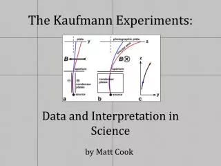
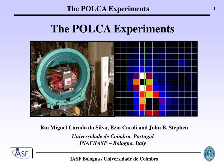
The POLCA Experiments. Rui Miguel Curado da Silva, Ezio Caroli and John B. Stephen. Universidade de Coimbra, Portugal INAF/IASF – Bologna, Italy. Klein-Nishina cross-section for linearly polarized photons:. 90º symmetry. . Polarization direction. . Q factor. (°).

E N D
The POLCA Experiments Rui Miguel Curado da Silva, Ezio Caroli and John B. Stephen Universidade de Coimbra, Portugal INAF/IASF – Bologna, Italy
Klein-Nishina cross-section for linearly polarized photons: 90º symmetry Polarization direction Q factor (°) Compton Polarimetry
100 % Polarised photons Energy range: 100 keV to 1 MeV j - angle between incident photon polarisation direction and the scattering plane. 128 128 CZT Pixel Matrix
100 keV 200 keV 300 keV 400 keV 500 keV 600 keV 700 keV 800 keV 900 keV 1 MeV Polarization direction Double interactions
Crab Balloon Satellite Minimum Detectable Polarisation
POLCA: POLarisation with CdTe Array European Synchrotron Radiation Facility Synchrotron ~ 99 % polarized radiation Beam line (ID15)
4x4 Monolithic CdTe Matrix Preamplifiers CdTe prototype tested at the ESRF under a 100% polarized beam
Double event distributions (90º symmetry) 7.5 mm 300 keV 400 keV Polarisation direction Beam Beam
Q factor comparison: experiment vs simulations POLCA experiment Monte Carlo
The Gamma-Ray Imager Mission for ESA Cosmic Vision Laue Lens Focal Plane
GRI main science requirements • Access to non-thermal Universe and gamma-ray lines: • cover soft gamma-ray energy range (~150 keV - 1 MeV) • Sensitivity leap in soft gamma-rays: reach 50 µCrab • Contemporaneous observation down to hard X-rays: 20 - 200 keV band • Polarimetry for identification of emission processes
GRI performance summary Requirements: baseline to fulfill GRI science objectives Goals: possible evolutions (to be studied)
GRI Focal Plane Instrument Courtesy INAF/IASF Roma CZT stack detector • - 4 detection planes; • - distance between planes: 20 mm; • - pixel area: 2.5×2.5 mm2; • - top layer: 5 mm thick • - 3 bottom layers are 20 mm thick • each plane equivalent: 160×160 mm (64×64 pixels) • 40 cm walls of 10 mm thick CZT • BGO veto shield
Laue Lens Development CLAIRE Ge crystal lens (integration) (courtesy: P. von Ballmoos) Cu crystal monochromator (courtesy: ILL) Lens requirements: Mounting and control of several 10 000 crystal is a technological challenge R&D work underway: CESR, Toulouse, France and Physics Department, University of Ferrara, Italy
Laue Lens Point Spread Function on the Focal Plane On Axis Laue Lens PSF @ 300 keV Off Axis (2’) Laue Lens PSF @ 300 keV
Experimental Setup of POLCA II • 150 keV to 750 keV energy range • ~ 99% polarised beam • 75 cm between crystals and detector
Polarisation direction 150 keV 250 keV Polarisation direction 450 keV 550 keV Double Event Maps Correction Method: Compton polarimetry 90º symmetry => extrapolation from 11×11 to a 21×21
Polarized Gamma-rays after Laue Diffraction For the first time polarized gamma-rays were observed after Laue crystal diffraction. (De Chiara and F. Frontera, Applied Optics, Vol. 31, 1992 and “Theory of X-ray Diffraction in Crystals”, Zachariasen, Dover Publications, 1994) Diffracted Beam Direct Beam
LaPOLCA The transmitted beam was left outside the sensitive area of the detector, except 345 keV for which the diffraction angle was too small. For each energy (90, 270 and 345 keV) =>16 measurements (3 laue lens rings) Simulation of a Laue lens ring: 1st step: rotation of the Cu crystal by step of 22.5⁰ 2nd step: move the detector to get the diffracted beam on Pixel 201 centre . 16th RTSD Workshop, Dresden, Germany 21 Ezio Caroli, INAF/IASF-Bologna, Italy
Future Steps • Experimental development • Two (or more) detection planes CZT stack • Experimental study of Laue lens composed by a greater number of crystals in a stable mechanical support; • Test and develop compatible electronic system • Monte Carlo Development • Prompt background due cosmic ray proton interactions, the delayed background due to decay emissions from material activation and the diffuse cosmic X-ray background; • SNR improvement using background reduction methods based on Compton kinematics; • Better modelling of the Laue lens PSF (vs E and off-axis sources)
The GRI consortium SRON (Utrecht) University of Utrecht CSR (Louvain-la-Neuve) DNSC (Kopenhagen) University of Coimbra University of Évora APC (Paris) CESR (Toulouse) CSNSM (Orsay) IAP (Paris) ILL (Grenoble) LAM (Marseille) IOFFE (St. Petersburg) SINP (Moskow) CNM (Barcelona) IEEC/CSIC (Barcelona) IFAE (Barcelona) MPE (Garching) Mullard Space Science Laboratory (London) Rutherford Appleton Laboratory University of Southampton INAF Brera INAF-IASF Bologna INAF-IASF Milano INAF-IASF Palermo INAF-IASF Roma Observatory of Roma University of Ferrara Argonne National Laboratory (Chicago) Space Science Laboratory (Berkeley)
Linearly polarized beam Non polarized beam Polarized Radiation
GRI science Gamma-rays probe non-thermal processes: particle acceleration, particle interactions, nuclear physics Gamma-rays are penetrating: probe deep into the central engines, e.g. supernovae or compact objects Gamma-rays are produced in a large diversity of emission sites:Sun, compact binaires, pulsars, SNRs, Galaxy/ISM, AGNs, GRBs Cosmic explosions Cosmic accelerators AGN/µQSO SN Novae Pulsars SNR
INTEGRAL: With GRI weintend: • to zoom in to identify the sources and to study their emission mechanisms • to understand the nature of this emission • to determine their high-energy spectra to measure their contribution to the galactic background • to identify it’s origin and measure e+ annihilation in individual sources • to understand the nature of supernovae explosions and their nucleosynthesis • reveals a large variety of gamma-ray source classes • discovers surprisingly hard emission from AXPs/SGRs • uncovers absorbed AGN • unveils a challenging positron annihilation sky map • provides a unique view on nucleosynthesis (26Al, 60Fe, 44Ti)
Gamma-Ray Imager Soyuz ST1
Polarization direction Double Event maps on each of the 7 plane a CZT stack 200 keV
No gap 0.2 mm pitch 0.2 mm pitch No gap GRI proposal simulations
POLCA II Prototype • Detector + Electronics • 40x40 mm2 CZT detector • 2.5x2.5 mm2 pixel • 5 mm thick • 16x16 pixels (active: 11x11) • ASIC readout electronics • Coincidence for double and multiple event detection • POLCA II Work Plan • Laue Lens crystal response analysed by a CZT matrix detector • Polarimetric response on the range 100 keV - 650 keV • Q factor vs the angle between polarisation vector and detector axis • Analog Front-End Electronics: • eV products 16 channels ASIC • Programmable peaking time and gain • Energy threshold (CZT): <20 keV • Power: ~10 mW/ch