Download
1 / 19
190 likes | 363 Views
MIT Compact X-ray Source . William S. Graves MIT March 27, 2006. ICS Operating Modes. High average flux optimized for protein crystallography and medical x-rays. 10 MHz repetition rate 5 x 10 12 x-rays per second (2 x 10 11 in 0.1% bandwidth) 0.1 nC charge per bunch

E N D
MIT Compact X-ray Source William S. Graves MIT March 27, 2006
ICS Operating Modes • High average flux optimized for protein crystallography and medical x-rays. • 10 MHz repetition rate • 5 x 10¹² x-rays per second (2 x 10¹¹ in 0.1% bandwidth) • 0.1 nC charge per bunch • 1 kW average laser power • High peak flux optimized for single-shot, time-dependent studies • 10 Hz repetition rate • 4 x 10⁹ x-rays per shot (goal is > 1 x 10¹⁰ per shot) • 1.0 nC charge per bunch • 0.2 kW average laser power Today’s focus
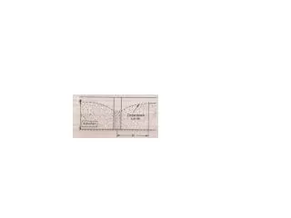
Large Time-Average-Flux Performance Results from 3D-code of W. Brown, MIT Lincoln Lab
High Flux-Per-Pulse Performance Results from 3D-code of W. Brown, MIT Lincoln Lab
ICS Modeling Results Results of 3D ICS code assuming design electron and laser parameters Electron Beam Parameters: E = 25 MeV enx = 0.3 mm b = 4 mm (rms spot size = 5 mm) Rms bunch length = 1 ps Charge = 0.1 nC Laser Parameters: W = 10 mJ zR= 0.3 mm (rms spot size = 5 mm) Rms Laser Duration = 0.5 ps l = 1.03 mm a0 = 0.063 Total X-ray dose per pulse = 6.2x10⁶ X-ray dose in 4 mrad full angle cone = 8.9x10⁴ Spectral Width (FWHM) in cone = 0.15 keV On-axis spectral width (FWHM) = 0.08 keV Rms source size = 3.7 microns Photons/pulse = 8.9 x 10⁴ FWHM = 0.15 keV (1.3%)
ICS Modeling Results Results of 3D code assuming design electron and laser parameters Intensity Profile of 12 keV X-rays With 0.4% Full Width Energy Filter 9 mrad 9 mrad diameter
Yb:YAG Oscillator Yb:YAG Pre ampl. pump diode SESAM Multi-passYb:YAG Amplifier Yb:YAG Power Supply 3 m Diodes 1.5 m LHe Dewar LHe Refrigerator MIT Inverse Compton Source Prototype 7 m Injector Power Supply Linac Power Supply Focusing quadupoles SRF gun Solenoid SRF linac Collimating chicane Photoinjector laser
Diode-pumped Photocathode Laser To achieve a homogeneous e-beam bunch Spatially parabolic beam 4th-Harmonic Generation with BBO crystals <0.5ps, 50nJ, 10MHz @257 nm Yb:YLF, 200 fs, 10 MHz, 20W, 1030 nm Beam shaper (parabolic beam)
Bi-Cavity Cryomodule Stainless steel vacuum vessel LN2 port Helium port He gas collector Titanium He vessel RF cavity RF couplers RF waveguides
RF Power At full gradient of 15 MV/m, 1 mA of current requires 15 kW of RF power per cavity. Need additional power for RF wall losses. 16 kW 1.3 GHz Inductive Output Tube (IOT) Operational frequency 1300MHz Beam voltage 24kV Grid bias voltage - 50V Output power 16.4kW Collector dissipation 5.1kW Efficiency 68.3% Drive power 63W Gain 24dB Bandwidth 5MHz Specification from CPI. Similar tubes available from Thales and EEV.
Preliminary Cryogenic Specification • Photoinjector • Static heat load 10 - 15 W. • Dynamic heat load <50 W for a gradient of 23 MV/m in CW operation. • Linac Bi-cavity module • Static heat load 10 - 15 W . • Dynamic heat load (RF dissipation) <105 W for a gradient of 15 MV/m CW. • Total • 180 W at full power in CW mode • Heat load scales as (beam energy)2 • Use standard Linde L140 or L280 LHe refrigerator Linde L280 LHe liquifier
Start-to-End Simulation • Goal is to generate a self-consistent simulation from the photocathode drive laser all the way through production and manipulation of x-rays • Include all photon and electron beam physics • Include optical and electron transport aberrations • Multi-dimensional, time-dependent codes • Report first results today – more optimization to be done.
RF Field Model of SRF Photoinjector Two dimensional model of cylindrically symmetric cavities Accelerating electric field lines Niobium cavities Beampipe exit FZR SRF 3.5 cell photoinjector modeled with standard RF design program SUPERFISH Photocathode
RF Field Model of Linac Cavity Two dimensional model of cylindrically symmetric cavities Beampipe entrance Accelerating electric field lines Beampipe exit Niobium cavities TESLA 9-cell cavity modeled by SUPERFISH
Accelerator Lattice Model Quad triplet #1 Dipole chicane Quad triplet #2 Lattice designed with MAD Dispersion reaches 38 mm in collimator Minimum beta function ~4mm at interaction point (IP) RMS size at IP = 7 mm Total demagnification = 1/45
Initial Conditions at Photocathode Surface electric field 33 MV/m Initial RF phase 80 degrees Parabolic laser intensity profile in each dimension. Thermal emittance reaches peak of 0.6 mm for edge radius of 1.5 mm Plot of x-y laser intensity on cathode Modest peak current of 25 Amp. FWHM = 4 ps Transverse parabolic profile is required, but can use arbitrary (short) longitudinal profile for charge < 300 pC See O.J. Luiten et al, Phys Rev Lett 93 (2004)
PARMELA Modeling Results Upper row shows beam properties at photoinjector exit. Lower row shows beam properties at interaction point. X vs RF phase Energy Emittance rms DE = 0.3 keV Thermal emittance is preserved from cathode to IP X vs RF phase Energy rms DE = 3 keV growth due to space charge Xrms = 7 mm at IP Emittance
Start-to-End Modeling Results Output of 3D ICS code using electron distribution from start-to-end Electron Beam Parameters: E = 25 MeV enx = 0.68 mm b = 5 mm (rms spot size = 8.6 mm) Rms bunch length = 2.1 ps Charge = 0.1 nC Laser Parameters: W = 10 mJ zR= 0.3 mm (rms spot size = 5 mm) Rms Laser Duration = 0.5 ps l = 1.03 mm a0 = 0.063 Total photons per pulse = 2.8x10⁶ Photons in 0.4% b.w. = 1.7x10⁴ On-axis spectral width (FWHM) = 0.2 keV Rms source size = 5.1 microns FWHM = 0.20 keV (1.7%)
Start-to-End Modeling Results Output of 3D ICS code using electron distribution from start-to-end Intensity Profile of 12 keV X-rays With 0.4% Full Width Energy Filter Photons/pulse = 1.67 x 10⁴