Download
1 / 10
100 likes | 214 Views
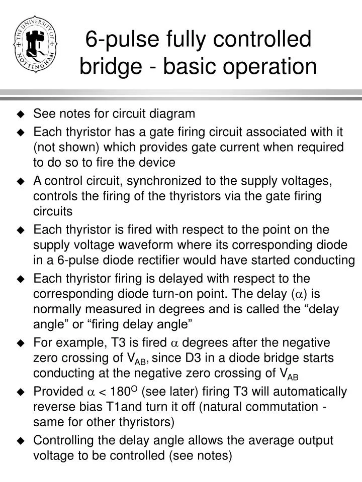
6-pulse fully controlled bridge - basic operation. See notes for circuit diagram Each thyristor has a gate firing circuit associated with it (not shown) which provides gate current when required to do so to fire the device

E N D
6-pulse fully controlled bridge - basic operation • See notes for circuit diagram • Each thyristor has a gate firing circuit associated with it (not shown) which provides gate current when required to do so to fire the device • A control circuit, synchronized to the supply voltages, controls the firing of the thyristors via the gate firing circuits • Each thyristor is fired with respect to the point on the supply voltage waveform where its corresponding diode in a 6-pulse diode rectifier would have started conducting • Each thyristor firing is delayed with respect to the corresponding diode turn-on point. The delay () is normally measured in degrees and is called the “delay angle” or “firing delay angle” • For example, T3 is fired degrees after the negative zero crossing of VAB,since D3 in a diode bridge starts conducting at the negative zero crossing of VAB • Provided < 180O (see later) firing T3 will automatically reverse bias T1and turn it off (natural commutation - same for other thyristors) • Controlling the delay angle allows the average output voltage to be controlled (see notes)
“Notching” - effect of overlap on supply voltage (1) • Affects diode and thyristor bridges - but is more pronounced with thyristor circuits • Consider the T1/T3 overlap • VAB is a sinewave • During overlap, Va’b’ = 0 (supply voltage is dropped across the supply inductance) • Va’b’ = has “notches” in it (where it falls to zero) each time there is a T1/T3 overlap (or a T4/T6 overlap) • The other 2 line voltages are also distorted at these points and have either a notch or a pulse 1/2 the size of the Va’b’ notch (see example) • Consequently each line voltage at the converter terminals has 6 notches (2 large ones dropping to zero and 4 smaller ones) corresponding to the 6 overlaps per cycle (see example)
“Notching” - effect of overlap on supply voltage (2) • Distortion due to notching is most severe at the converter terminals but distortion is seen at other points in the network since the supply inductance is distributed • PCC - Point of Common Coupling. Place where other users are connected to the network and normally the point where power quality regulations are applied • Distortion due to notching at PCC is attenuated from that at the converter terminals by the ratio L1/(L1+L2) • L2 often added inside the equipment to reduce distortion seen by the network • Note - large notches occur degrees after each zero crossing of the line voltage. Notches are very large for values of around 90O - hence generally worse with thyristor circuits rather than diode circuits
“Notching” - example to do • Doing this example will test your ability to draw rectifier waveforms and will clearly illustrate the distortion caused by notching • On a 3-phase template, draw VXN, VYN and VXY for a firing delay angle of 60O and an overlap angle of 15O • Label next to each overlap, the thyristors involved in each overlap • Draw up a table listing the overlaps in order and, corresponding to each overlap, the voltages Va’N and Vb’N. Hence determine the voltage Va’b’ at each overlap and add this to the table • Hence draw the waveform of Va’b’ and see the distortion due to notching. Note that Va’b’ = VAB except during overlaps
Fully controlled Bridge - Inverting Operation • If > 90O then the mean converter output voltage (VXY) will be negative and power can flow from the DC side to the AC side - this is called INVERSION • For this to be sustainable there must be a source of energy on the DC side - eg battery, or motor acting as a generator • Very useful when the converter feeds a motor since it allows mechanical energy to be returned to the supply (useful to avoid energy wastage when slowing things down - see H5CEDR) • Theoretically can be taken to 180O during the inverting mode, but in practice it is limited by the need to provide sufficient reverse bias time for the thyristors to turn off properly
Fully controlled Bridge - Maximum delay angle (1) • Consider commutation from T1 to T3 • T3 is fired degrees after the negative zero crossing of VAB. There is then an overlap with T1 and T1 turns off (+) degrees after the negative zero crossing of VAB. After T1 has turned off, the voltage across it is VAB. • T1 will be reverse biassed after turn-off for a time equivalent to [180 - (+)] degrees.
Fully controlled Bridge - Maximum delay angle (2) • In seconds, the reverse bias time is given by • trv = [180 - (+)]/180 • For T1 to turn off properly, trv must be greater than the turn off time (normally given the symbol tq) for the particular thyristor used. • It it isn’t, T1 will start conducting again when VAB goes positive (even though it isn’t fired) and a catastrophic short circuit of the DC side will occur when T4 is fired • This is called a COMMUTATION FAILURE and can normally be recovered from by blowing fuses • To avoid commutation failure (+) is limited to typically 150O • Even so commutation failure can occur in practice due to abnormal conditions such as: • Excessive DC side current, resulting in an increase in • Reduction in supply voltage, resulting in an increase in • too large due to control circuit error (loss of synchronisation for example)
Dual Controlled Bridge - 4 Quadrant Arrangement(1) • Very important for DC machine drives • One fully controlled bridge can provide 1 direction of current and both polarities of voltage • For a DC machine Voltage Speed and Current Torque • Hence a single bridge can drive a machine in 2 “quadrants” of the torque-speed plane • Many applications require operation in all 4 quadrants (accelerating and braking in both directions) • Need to use 2 bridges in a dual arrangement • Very common arrangement for DC motor drives
Dual Controlled Bridge - 4 Quadrant Arrangement(2) • At any time, only one of the bridges is enabled (otherwise the supply would be short circuited) • The controller must sense the desired current direction and enable the appropriate bridge.
Inverting operation - example to do • Doing this example will (definitely!) test your ability to draw rectifier waveforms and will clearly illustrate the reverse bias period following thyristor turn off • On a 3-phase template, draw VXN, VYN and VXY for a firing delay angle of 120O and an overlap angle of 15O • Label next to each overlap, the thyristors involved in each overlap. Label the conducting thyristors during the non-overlap periods • Draw up a table listing the thyristor conduction patterns in sequence (including overlaps) for a whole cycle. • Next to each conduction pattern, tabulate the voltages VXN and Va’N and hence tabulate the voltage VT1 (voltage across thyristor 1) • On another template re-drawVXN, VYN on the upper part and using the table, draw VT1 on the lower part • Make sure you can identify the reverse bias time on the VT1 waveform and make sure it is equal to [180 - (+)] degrees • Note: this exercise will take some time and methodical working to do - but it will be invaluable practice