Download
1 / 22
220 likes | 358 Views
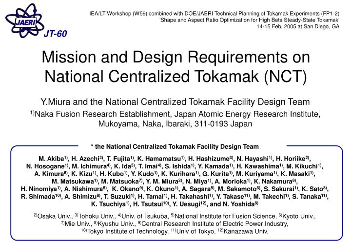
IEA/LT Workshop (W59) combined with DOE/JAERI Technical Planning of Tokamak Experiments (FP1-2) 'Shape and Aspect Ratio Optimization for High Beta Steady-State Tokamak’ 14-15 Feb. 2005 at San Diego, GA. JT-60. Mission and Design Requirements on National Centralized Tokamak (NCT).

E N D
IEA/LT Workshop (W59) combined with DOE/JAERI Technical Planning of Tokamak Experiments (FP1-2) 'Shape and Aspect Ratio Optimization for High Beta Steady-State Tokamak’ 14-15 Feb. 2005 at San Diego, GA JT-60 Mission and Design Requirements on National Centralized Tokamak (NCT) Y.Miura and the National Centralized Tokamak Facility Design Team 1)Naka Fusion Research Establishment, Japan Atomic Energy Research Institute, Mukoyama, Naka, Ibaraki, 311-0193 Japan • * the National Centralized Tokamak Facility Design Team • M. Akiba1), H. Azechi2), T. Fujita1), K. Hamamatsu1), H. Hashizume3), N. Hayashi1), H. Horiike2), • N. Hosogane1), M. Ichimura4), K. Ida5), T. Imai4),S. Ishida1), Y. Kamada1), H. Kawashima1), M. Kikuchi1), A. Kimura6), K. Kizu1), H. Kubo1), Y. Kudo1), K. Kurihara1), G. Kurita1), M. Kuriyama1), K. Masaki1), M. Matsukawa1), M. Matsuoka7), Y. M. Miura2), N. Miya1), A. Morioka1), K. Nakamura8), H. Ninomiya1), A. Nishimura5), K. Okano9), K. Okuno1), A. Sagara5), M. Sakamoto8), S. Sakurai1), K. Sato8), R. Shimada10), A. Shimizu8), T. Suzuki1), H. Tamai1), H. Takahashi1), Y. Takase11), M. Takechi1), S. Tanaka11), K. Tsuchiya1), H. Tsutsui10), Y. Uesugi12), and N. Yoshida8) • 2)Osaka Univ., 3)Tohoku Univ., 4)Univ. of Tsukuba, 5)National Institute for Fusion Science, 6)Kyoto Univ., • 7)Mie Univ., 8)Kyushu Univ., 9)Central Research Institute of Electric Power Industry, • 10)Tokyo Institute of Technology, 11)Univ of Tokyo, 12)Kanazawa Univ.
New Minimum Step to Fusion Power NCT Previous Strategy Proto DEMO Large Tokamaks ⑤Economical feasibility Commercialization ③SS plasma ④Power production JT-60(JA) JET(EU) TFTR(US) ①Self-sust. burn ②Long burn ITER To establish vision for commercialization for a period of 2030-2050, it • should operate in steady state (for example, continuously for 1year) • should achieve high beta (N=3.5(SSTR)-5.5(CREST)) • should operate reliably (less than 1 off-normal event in 2 years) at least towards the end of operating period. Recent strategy ITER Commercialization DEMO Large Tokamaks Demonstration of SS operation High b SS JT-60 TFTR →NCT JET
NCT is a domestic research program for advanced tokamak research to succeed JT-60U incorporating Japanese universities accomplishments NCT Collaborating Universities or Institutes in FY2004. Stratified Structure of Fusion Research Realization of Fusion Energy Developmental ITER Tokamak IFMIF Helical Laser (Developmental) (Academic) Fusion Science Reactor engineering Plasma Science Academic Research Basis Academic
Mission of National Centralized Tokamak NCT ferritic steel • Establish high steady state operation for DEMO and Contribute to ITER • Demonstrate high (N=3.5-5.5) non-inductive operation for more than 100 s in collision-less regime • Test compatibility of reduced activation ferritic steel • Demonstration of ultra-long (~8 hours) steady state operation
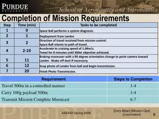
Requirements of NCT machine capability NCT Cryostat TFC PFC R F Present equipment in JT-60 (reuse) P-NBI P-NBI 15 m N-NBI VV reuse Sector Coil Stabiliser Plate Divertor 13.5 m • A super-conducting device with break-even-classplasma performance • Capability of steady state high- (N=3.5-5.5) plasma with full non-inductive current drive, required for the DEMO for more than 100 s • Flexibility in terms of plasma aspect ratio, plasma shaping control, and feedback control best use of existing JT-60 infrastructure
Heating and Current Drive systems for NCT NCT 1. P-NB(85keV)/ Co-injection : 4 units Current Profile control 2. P-NB(85keV)/ Counter : ??? Rotation control 3. P-NB(85keV)/ Perpendicular: 8 units Heating Profile control 4. N-NB(350-400keV)Co-inj. : 2 units Current Profile control 5. ECW : 110GHz, 4 units NTM suppression P-NB: 85 keV Tang.: 4 units Perp.: 8 units ECW: 110GHz 4 units possible upgrade N-NB: 350-400 keV Tang.: 2 units
Higher Plasma Shape for a High-N NCT JT-60 ASDEX-U JET DIII-D S=2.3-7.4 S=3.1-3.6 S=3.0-5.4 S=2.0-2.2 6 5 4 3 2 Research target of NCT Normalized bN DIII-D experiment JT-60 ITER Ip q95 S 2 3 4 5 6 7 aBT Shape parameter S ~ A-1{1+k2(1+2d2)} • Extension of the flexibility in the plasma shape is key issue for a high-bN plasma operation where the research target of NCT is addressed. Observed in DIII-D experiment [M.R. Wade et al., PoP 8 (2001) 2208] • In order to improve a shape parameter, low aspect ratio as well as high elongation and high triangularity is considered in NCT design. Presented by T.S. Taylor at DOE/JAERI Technical Planning of Tokamak Experiments and Large Tokamak Workshop in Naka at 7-8 Feb. 2001
Two Options of NCT (NCT-1 & NCT-2) NCT NCT-1 NCT-2 400 turn 4m 432 turn NbTi NbTi NbTi Nb3Sn NbTi 294 turn 144 turn 168 turn NbTi 144 turn NbTi Ip=4.0MA Bt=3.43T A=2.85 k95=1.57 Ip=5.5MA Bt=2.76T A=2.6 k95=1.84 144 turn 6m 6m NbTi NbTi 96 turn 144 turn Nb3Sn NbTi NbTi 418 turn 160 turn Nb3Sn 208 turn Nb3Sn -4m 540 turn 400 turn
Typical Plasma Parameters for 2 Options with SN & DN NCT 2 1 3 4 NCT-1 NCT-2 1 m 1 m 1 m 1 m
Divertor Pumping is important for long pulse operation- Design Criteria for Divertor Geometry- NCT Cryopanel Pump S Outside divertor Inside divertor Leg l For divertor performance S≥ 100m3/s, l≥ 0.4m S. Sakurai et al., Plasma Phys. Cont. Fusion 44 (2002) 749. Criteria of k is estimated for given A, d to ensure the divertor pumping and leg length. NCT-2 NCT-1 high-k, d, and low-A makes divertor narrow dx=0.55
Optimization of Shape Parameter by A and, 5 Stabilizer for NCT-2 DN NCT 4 3 2 Z (m) 1 0 -1 -2 -3 -4 1 2 3 4 5 R (m) -5 3.5 Aspect Ratio A 3.0 Divertor Pump 2.0 4 5 6 7 8 2 3 Shape Parameter S Matsukawa’s presentation Criteria : Divertor pumping speed ≥ 100m3/s -> X-point height limit Leg length limit • - With the trade-off of divertor pumping, S-parameter goes up to 8 at A ~ 2.6 in NCT-2 design. • With the divertor pumping of ≥100 m3/s, S-parameter ~ 7 is expected. • - Restrict of causes the decrease of S in low A. Flexibility in plasma shape and aspect ratio is extended in consistent with the sufficient divertor performance.
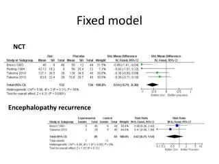
Critical N for MHD stability on Plasma Aspect Ratio NCT 9 Double null k95 = 1.8 Negative shear qmin= 2.4 Parabolic P(r) A=2.5(n=1) A=2.5 (n=2) A=3.0 (n=1) 8 A=3.0 (n=2) bN 7 Critical 6 5 4 3 1.2 1.4 1.6 1.8 2.0 2.2 2.4 2.6 r /a w NCT design Kurita’s presentation • Dependence of critical bN on plasma aspect ratio for n=1 and n=2 mode is estimated as a function of the ratio of rW/a (ERATO-J code). • Critical bN increases in lower aspect ratio, which suggests the advantage of low aspect ration on N. • optimization of pressure profile is being studied. • Critical N dependence on shape factor S will be presented by Kurita’s talk.
High N together with large QDTequ. NCT • NCT should have a potential to investigate high N at large QDTequ • conditions: q95~3.5, PNB=25MW, HHy2=1.5, fGW=0.5-1 • In the case of N~5.5, QDTequ <0.2 • In the case of QDTequ~1 with fGW ~0.6-0.8, N ~2.6-3(NCT-1), N ~2.9~3.3(NCT-2)
Parameters of * and * for two options NCT • In the regime of N=2.5-5.5, *<0.01 for fGW=0.5-1.0. • Conditions: • q95~3.5, • PNB=25 MW, • HH(y,2)=1.5, • fGW=0.5-1.0 ITER ITER
High N with full non-inductive scenario NCT • 15MW with HHy2=1.5-1.6(25MW with HHy2=1.2-1.3), It is possible to have 1.5-1.7MA plasma with high N and full CD conditions • For q(0)>1, it is necessary to increase q95 (because of the central CD). A=2.6,1.7MA, 1.5T, q95=8.8, bN=3.6, HHy2=1.64, fGW=0.63 PNB A=3.3,1.5MA, 1.8T, q95=5.1, bN=3.7, HHy2=1.51, fGW=0.50 NNB PNB PNB jTOTAL fBS=0.68 jTOTAL jBD jBD fBS=0.60 jBS NNB jBS PNB
For a high performance, off axis N-NB is a candidate NCT P-NB N-NB • By a modification of N-NB beam line, it is possible to increase performance of high-N with full CD. • The modification increases the capability of the current profile controllability. • A=2.6, Ip=3.0MA, Bt=2.1T, q95=6.1, qmin=2.0, N=4.0, HHy2=1.99, fGW=0.50, N-NB (3MW, 400keV), P-NB (22MW, 85keV) NCT-2 jTOTAL jBD jBS fBS=0.69
Controllability of ECCD for NTM suppression NCT 1 0.5 0 Controllability of ECCD is estimated by ray-tracing and Rutherford equation to deduce the required power. normal shear with qo=1 fECE= 110 GHz For m/n=3/2 mode in low-A, slightly high power is required due to the bload resonance width. Required power is available for 30 s r 6 4 2 0 Drive current density (MA/m2)
Heat and Particle Control NCT ・ FW + SOL widthlimit ・ a and IP is increasing ・ a=0.7m : constant ・ Plasma moves to inside -> higher IP -> higher BT -> higher density First wall + SOL width VV Stabilizer TFC Divertor Region ・ Constant IP Density window for NCT-1 & 2 ~ same • high pumping capability is set on NCT • To reduce divertor heat load and to keep plasma clean, the higher density is better Radiation Power Zeff Zeff, Radiation Power required radiation power ~imput power-10MW Density
Assessment of Two options NCT There is a strong probability that NCT-2 option will be National Centralized Tokamak
Day long operation NCT • Plasma-wall-interaction with a long time scale (~8 hours) • Avoidance of disruption against the external perturbation
Example of Day-long operation NCT • Demonstration of controllability for ultra-long time scale Example simulation for day-long operation available both in NCT-1 and NCT-2 BT=1.3T IP=1MA Rp=2.85m ap=0.85m q95=5 k95=1.76 d95=0.46 Vp=70.7 m3 bN=3.66 W=2.36 MJ tE=0.236 sec HHy2=1.6 Zeff=1.5 (O2) PNBabs=7.73 MW neav=3.36e19m-3 fGW=76% fBS=56% QDTeq=0.143 Pfusion=1.1 MW Full CD
Summary NCT • Design of NCT is in progress to establish high steady state operation for DEMO and to contribute to ITER • The shape and aspect ratio are important parameters for NCT. • Recent evaluation for the designs, there is a strong probability that NCT-2 option which has A≥2.6, ≤2, S≤7 and BT≤3T will be selected as National Centralized Tokamak.