Download
1 / 18
190 likes | 381 Views
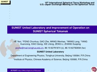
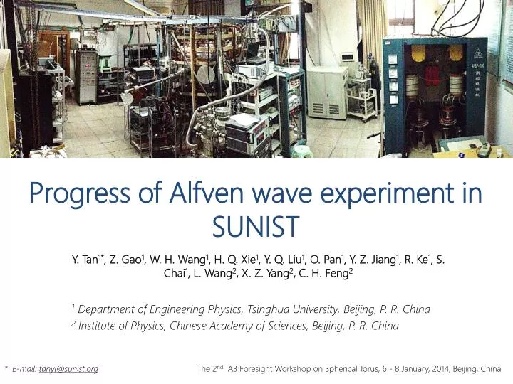
Progress of Alfven wave experiment in SUNIST. Y. Tan 1* , Z. Gao 1 , W. H. Wang 1 , H. Q. Xie 1 , Y. Q. Liu 1 , O. Pan 1 , Y. Z. Jiang 1 , R. Ke 1 , S. Chai 1 , L. Wang 2 , X. Z. Yang 2 , C. H. Feng 2. 1 Department of Engineering Physics, Tsinghua University, Beijing, P. R. China

E N D
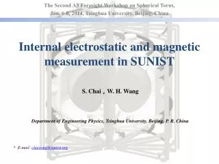
Progress of Alfven wave experiment in SUNIST Y. Tan1*, Z. Gao1, W. H. Wang1, H. Q. Xie1, Y. Q. Liu1, O. Pan1, Y. Z. Jiang1, R. Ke1, S. Chai1, L. Wang2, X. Z. Yang2, C. H. Feng2 1 Department of Engineering Physics, Tsinghua University, Beijing, P. R. China 2 Institute of Physics, Chinese Academy of Sciences, Beijing, P. R. China * E-mail: tanyi@sunist.org The 2nd A3 Foresight Workshop on Spherical Torus, 6 - 8 January, 2014, Beijing, China
Contents • Basic Principle • Motivation • Research Plan • Recent Progress • Future Work • Summary
Basic Principle • Excite a rfB field in the vacuum • with a specific spatial structure (k) by a set of antenna • Rf B field spreads into plasmas • becomes Compressional Alfven Wave (CAW) • CAW Shear Alfven Wave (SAW) Kinetic Alfven Wave (KAW) • at Alfven resonance surfaces (where VA ~ wave phase velocity vp) • Transfer energy to electrons • and may drive current if v|| ~ wave phase velocity vp Rf current Resonance layer Rf Generator Plasma Z axis Antenna
Motivation • Is AW a high efficiency current drive method? • Yes, if no trapped electrons • No, if most electrons are trapped (ST) • Unsure theoretically, if the moment can be recovered by some special process • AWCD on SUNIST • Try to verify the possibilities of moment recovery experimentally Ehst and Karney, NF, 1991, Gao, A3 SS, 2013
Motivation (continued) • Is SUNIST suitable for the study? • Trapped ratio is significant (100 eV, from simulation results of single particle’s motion) • Operation space for exists Trapped ratio of 100 eV electrons in SUNIST Effective space L Zhang, PhD dissertation, 2009
Research Plan Hardware design, manufacture upgrade Coupling study (small power) Current status upgrade Heating and current drive (high power)
Recent Progress • Setup of the experimental system • Coupling study without antenna limiters • Installation of the antenna limiters • Coupling study with antenna limiters • Setup of a new rf generator
Setup of the experimental system • The RF generator • Four phases outputs • But only two phases are stable • 20 ~ 50 kW, 0.4 ~ 1 MHz (not continuous) • Antennas • No shielding, no limiters • Two of four pairs used • phasing • |N|=1 ~ 60%, |M|=1 ~ 15% • Plasma parameters • IP:30~50 kA • ne:0.5 ~ 319 m-3 • BT:800~1200 G Toroidal arrangement of the antennas antennas Plasmas and the antennas without protector
Coupling study • Antenna impedance measurements • Low frequency Z = U/I is viable • I: rf current transformer (Pearson Model 110) • U: rf voltage transformer (homemade) URF measurement IRF measurement Vacuum results
Coupling character without antenna limiters • Have similar trends as 1-d calculations Experimental results (left) and theoretical results (right) of the impedances of antennas
Installation of the antenna limiters • Side limiters made by boron-nitride plates have been proven to be effective in Phaedrus-T With BN limiters With Faraday screen Impurity lines of the AWCD experiments in Phaedrus-T tokamak Sorensen, NF, 1996
Installation of the antenna limiters (ctd.) • Two limiters have been installed now Design sketch Boron-nitride protected antennas in the vacuum vessel Tan Y, et al. FED 13, 30
Installation of the antenna limiters (ctd.) • The effects of BN limiters are obvious Shot 130627007, without BN limiters Not stable Stable operation Effective protection Stable operation with BN limiters
Coupling character with antenna limiters • Plasma parameters • IP ~ 50 kA, neL ~ 1E19 m-2 Stable operation Antenna loading decreased • coupling weakened • offset of the limiters may be too much Antenna loading vs. BT in different discharges
Setup of a new rf generator • A new four phase rf generator has been installed on SUNIST • 0.56 ~ 1.6 MHz / 4 X 25 kW Stable operation The new rf generator of SUNIST Arbitrary phase adjustment
Future Work • Ohmic discharges need to be improved further • A stable density is required for AW experiments Stable operation Typical ohmic discharge waveforms with different gas puffing
Future Work (continued) • Flexible configurations of aspect ratio • For better understanding of the shaping effects Inner limiter Movable limiter plasma Outer limiter plasma Stable operation High A Low A
Summary • The coupling character of Alfven wave has been studied experimentally • Coupling is more strong without limiters than with limiters • In the future • Re-investigate the coupling using new rf generator under higher and flexible plasma parameters • Thanks Stable operation