Download
1 / 42
420 likes | 558 Views
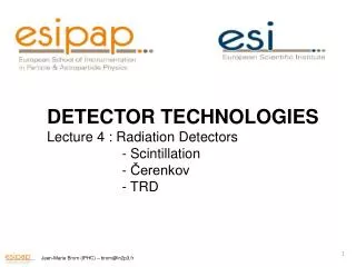
DETECTOR TECHNOLOGIES Lecture 2: gazeous détectors Principle of operation Proportional counters and beyond. Gazeous detectors : Principle of operation.

E N D
DETECTOR TECHNOLOGIES Lecture 2: gazeousdétectors Principle of operation Proportionalcounters and beyond
Gazeous detectors : Principle of operation E. Rutherford and H. Geiger (1908) "An electrical method of counting the number of α particles from radioactive substances," Proceedings of the Royal Society (London) 1. A chargedparticleis passing trough a gazeous medium : loss of energy Ex : proton 1 GeV/c2 1.2 MeV K = 4 πNA re2 me = 0.3071 A, Z : atomic mass and number relative to the medium NA : Avogadro’s number Tmax : maximum possible energy transferred to an electron in the medium z : charge of the incoming particle , : relatives to the particle
Gazeous detectors : Principle of operation 2. : Ionization Energy corresponds to the energy required to remove a single electron from a single atom (or molecule). Approximation : 3. If One or more pairs electron – ion iscreated > 4. If exists an electricalfield : Electrons (and ions) are drifting… Signal…
Gazeous detectors : Principle of operation First example : Geiger-Muller counter Radial Electricalfield : ra = anode radius r = counter radius Signal Example : r = 1 cm Gas : Argon particle = MIP 120 pairs C = 10pF Signal : 2 µV Where Extremelyweak signal… But : whatcan append to the electrons (and ions) during the drift before collection ? It depens on the Electricalfield (applied voltage)
Gazeous detectors : Principle of operation Attachement : E islessthan the ion properfield e- - ion recombination - almost no signal Collection - Ionizationchamber :All e- are driftingtowards the anode. Weak signal (typically 1 e- for 30 eV) Multiplication - proportionnalregime : E bigenough for accelerating e-aboveEi Production of secondary e- … Avalanche
Gazeous detectors : Principle of operation Saturation and Streamer mode - Geiger-Muller regime : Electronic avalanche amplified by desexcitaion of ions Saturation of the signal. Loss of proportionnality Breakdown : Continuousdischargesbetween anode and cathode… Ultimate destruction…
Gazeous detectors : Principle of operation Transport of electrons and ions in the gas: With an electricfield, electrons and ions are acceleratedalong the fieldlines. Theirmovementisinterrupted by collisions (mean free path…) whichlimit the maximum averagevelocity. This drift velocityislow compare to the thermal velocity. Ions The ion collection time isdeterminant ! Electrons
Gazeous detectors : Principle of operation Choice of gas: Of course, ionizationexists in any possible gas. - Maximum gain (primaryelectrons) - Applied voltage as low as possible - Avalanche with a good proportionnality - Drift velocity as high as possible A good compormise : Noble gas (Ar, Xe, Ne...) : For example : Argon : 30 primaryelectrons Possible gain 103 – 10 4 e – drift velocity : 100 µm/nsec. at E = 1kV/cm Limitation : Noble gas have an high excitation energy (typically 10-12 eV). Excitedatomsformed in the avalanche desexictegiving photons whichcanionize, causingfurther avalanche… … Possible discharges. Solution : the quencher
Gazeous detectors : Principle of operation Quencher : one has to add a polyatomicgas in order to absorb the photons aither by multiple collisions or molecule dissociation Usually CH4, CO2, CF3, C2H4 …. With a mixture of Noble gas – Quencher, one canachievegains up to 106 - 107 MagicGas : 70% Ar, isobutane 29.6%, Fréon 0.4% . Problem : after dissociation, the organicmoleculeswillpolymerize on the anode. Loss of efficiency Needgas circulation One has to addanother agent…. (alcohol…) One of the BEST possible choice : DME : Dymethylether CH3OCH3 No polymerization Good gain (106) But itis a solvant !
Gazeous detectors : Principle of operation Basic requirement for a gas detector : determination of particletrajectories Recipe for a Gas detector - Thin (minimization of de/dx, does not perturb the particletrajectory) - Maximum gain (choice of gas) - Stability(High Voltage, choice of quencher) - Choice of material(to avoidpolymerization) - Precision Evolution fromGM countertoMultiwireProportionalChamber (MWPC) G. Charpak and all., 1968
Gazeous detectors : MWPC An array of closelyspaced anode wires in the same volume Cathodes Anodes Is equivalent to Anodes Cathodes An array of proportionalcounters tubes
Gazeous detectors : MWPC Classical figure of electricalfielddisturbed by a misplaced anode wire
Gazeous detectors : MWPC Signal Signal : as seen for the GM proportionalcounter : For an MWPC chamber ( L >> d >> s ) L d s Spatial résolution : The charges due to the particle passing in the gas are distributed over more than one anode. The spatial resolution of a MWPC is the variance of this distribution . Typically ≈ 200 µm Signal formation time : depens on the drift time for electrons (typically 50 nsec) Dead time :depens on the drift time for the ions (typically 200 nsec)
Gazeous detectors : MWPC limitation s Limitation 1 : Typically : anode spacing of the order of 1-1.5 mm (Résolution ≈ 200 – 500 µm) In order to improve the spatial résolution : closer anodes ? Does not work. Instabilities due to electrostatic forces anode-anode. Limitation 2 : MWPC canmeasureonly one coordinate. A second MWPC ? X-Y coordinatewith a second anode row Precision : σ One canreduce the wirespacing… Or increase L (dimensions…) α X Y X Y X Y L
Gazeous detectors : MWPC evolution Cathode read-out chamber : One anode plan Segmented cathode plan Analogread-out Experiment R704 (CERN ) 1981 - 1985
Gazeous detectors : Pad chambers Direct 2-D detector : Pad chambers cathode segmented in pads Needs a lot of electronics Pads regrouped in cells PHENIX
Gazeous detectors : Pad chambers PHENIX at RHIC
Gazeous detectors : Drift Chambers A drift chamber is a particle tracking detector that measure the drift time of ionization electrons in a gas to calculate the spatial position of ionizing (charged) particle. Similar to MWPC, but with a better accuracy. Measure of the position of the particle by mesuring the drift time of the electrons Need : Precise knoweledge of drift velocities Precise timing (trigger) Scintillator (start) SPACE-TIME CORRELATION (RIGHT-LEFT AMBIGUITY) Possible resolution down to 50 µm X = Vd ∆t
Gazeous detectors : Drift Chambers Main limitation : non-uniformity of the field (non uniformity of the drift time) Solution : defining a cell(basic unit of field) PHENIX (RHIC) Drift Chambner
Gazeous detectors : Drift Chambers 1 cell = 7.5 cm x 6.6 cm 12 layers Lenght : 2.3 m Radius : 1.6 m 5732 sensewires (anodes) 31104 potentialwires Gas mixture : 89% Ar, 10% CO2 ,1% methane Gain : 2 10 4 Drift filed : 900 V/m Spatial resolution : ≈ 150 µm MarkIIbig Drift Chamber
Gazeous detectors : Drift Chambers 370 000 tubes Surface 5500 m 2 Gas : Ar –CO2 (97-3 %) at 3 Bars Voltage ≈ 3120 V Max couting rate : 20 Hz / m Gasleak < 10 -8 Bar.l / sec. Wire tension tolerance 17g Wire position tolerance : 25 µm
Gazeous detectors : Time Projection Chambers TPC : « The best of the best evolution » Combination of a Drift Chamber and a MWPC (Pad chamber) Position (X and Y measurements) Drift time (Z measurement) Huge (and empty) drift volume Multi channels (read out pads) Drift volume full of ions séparation for the avalanche region
Gazeous detectors : Time Projection Chambers – The ALICE TPC at LHC
Gazeous detectors : Time Projection Chambers – The ALICE TPC at LHC
Gazeous detectors : Resistive Plate Chamber RPC : Thin (2 mm) drift volume sandwichedbetween Twohighlyresistive (2.5 1010Ω.cm) plates Simple – inexpensive – fast (used as rigger) Thin drift volume and High field Works usually in streamer mode Large signal, but slow (100 nsec) At LHC : in avalanche mode Lower signal, but fast (1-10 nsec)
Gazeous detectors : Resistive Plate Chamber for CMS - LHC Resistive plates : 1 1012Ω.cm Gas mixture : C2H2F4 (92.5 %)–C4H10 (4.5%) – SF6 (0.3%) HV : 8.5 – 9.7 kV RPC efficiency > 97% Rate capability > 1 KHz/cm2 Operation efficiency plateau > 400V Time resolution < 3ns Cluster size < 3 Dead time should be few nano seconds
Gazeous detectors : Straw Chambers SWPC : Single WireProportionalChamber Single proportionalcounter in an array - Cheap and simple to build - Capable of withstandingvery high fluxes
Gazeous detectors : Straw Chambers Straw Chambers : the ATLAS read-out system for the Transition Radiation Tracker
Gazeous detectors : MicroStripsGas Detector MSGC : following an idea of Oed (1989) : A MWPC where the wires are replaced by stripsdeposited on an insulatingsubstrate (glass) High field : gain ≈ 10 4 Spatial resolution : σ≈ 20 µm Dead time ≈ 10 -5 sec. (Short distance for the ions) Gas : Ar – DME / Ne - DME
Gazeous detectors : MicroStripsGas Detector MWPC MSGC anode spacing : 1-3 mm anode spacing 200 µm Rate capabilitycomparison MSGC seems to bewelladapted to high fluxes of particles(LHC)
Gazeous detectors : MicroStripsGas Detector Surface charging : Bulk or surface resistivity of the support materialismodified by irradiation (flux) Choice of support (special glass or doping) Ageing : Polymerization due to construction material (DME is a solvant) Choice of non-sovablematerial in DME Discharges: Possible withhigher flux or lowenergeticparticles Certain withdust (short between anode and cathode (50 µm)
Gazeous detectors : Gas Electron Multiplier GEM (on a MSCG) : préamplification at ≈ 100 µm above the substrate kapton foil (coppercoated) with amplification holes Dischargeprobability using single, double and triple GEMs
Gazeous detectors : MSGC + GEMs Compass
Gazeous detectors : Micromegas Micromegas : (G. Charpak and Y.Giomataris– 1992) issimilar to a MSGC+GEM and a drift chamber. The cathode is a mesh at 100mm from the anodes (stripdepsited on a substrate)
Gazeous detectors : Micromegas Limitation : Meshspacers (loss of acceptance) Prototype (1997)
Gazeous detectors : Micromegas Compass Set of 12 plates 40x40 cm 2 T2K / TPC Set of 12 plates 40x40 cm 2